[Mini Sharing] BIM-Based MEP Detailed Design
WeChat Sync · Xiaowei · 2024-04-26
The following article is sourced from M&E Connections
#1Contents of M&E detailed design
Specific contents of calculation verification for M&E installation engineering: head calculations for fans and air-conditioning units, verification of water pump head calculations, duct cross-sectional areas, pipe diameters, noise, vibration isolation, expansion joints, insulation, hydraulic balance, sprinklers, etc.
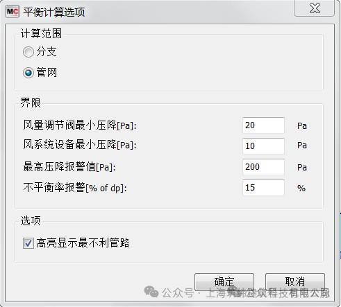
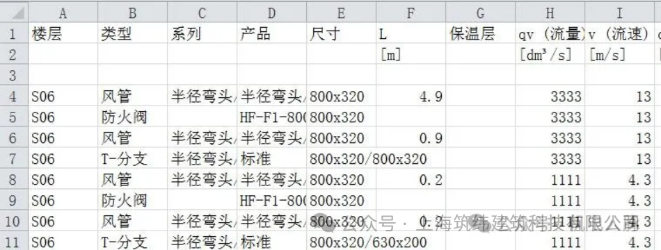
Duct hydraulic calculations
Main electrical discipline parameter verifications include: current load calculations, switchgear verification calculations, cable voltage drop calculations, cable tray specification calculations, illuminance calculations, power density value calculations, etc.
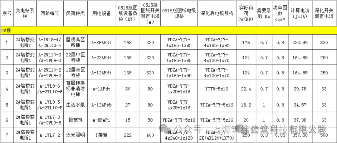
1) Verification method for load calculations
In conventional super high-rise projects, the demand factor method is used for load calculations according to the nature of electrical loads at different levels. Based on the electrical system diagrams and floor plans, the total equipment power and calculated current data required for each load are computed: the total equipment power at a distribution point is taken as the sum of the equipment power of all connected electrical equipment, with single-phase equipment evenly distributed across the three phases so that the calculated loads of the phases are as close as possible, reducing unbalance.
2) Verification of circuit breaker selection for distribution boxes
Using data from the load calculation sheets, verify whether the calculated current in each circuit falls within the circuit breaker's safe protection range, and verify whether the breaker's protection functions meet the load's power supply needs: following the principle of multiplying the calculated current of the load capacity by a load factor (power equipment: 1.25 times; lighting systems: 1.1 times; elevator systems: 1.4 times), select an incoming circuit breaker with a rated current that satisfies this value.
3) Verification of cable selection
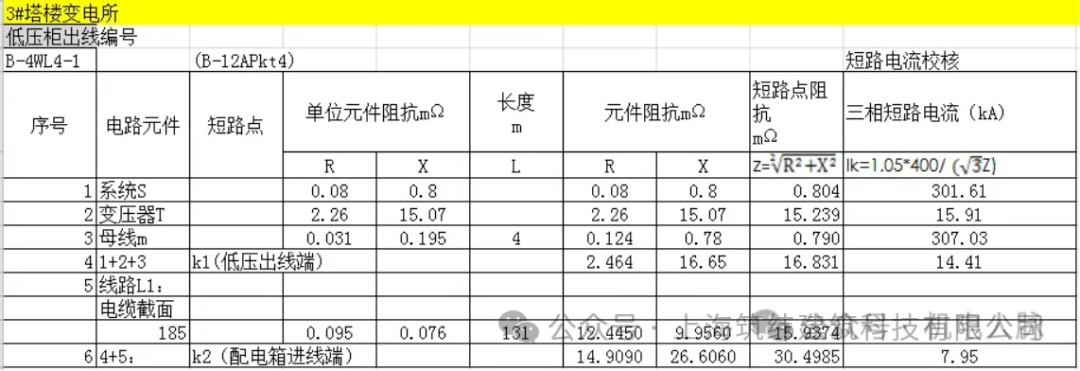
Collect from suppliers the cable current-carrying capacities, correction factors for different ambient temperatures, and adjustment coefficients for different laying arrangements; calculate the actual current-carrying capacity of the cables applied in the project; and select cables according to the principle that the incoming cable's current-carrying capacity must exceed the switch setting value. For each distribution system circuit, select the most unfavorable point and, based on the unit impedance value and end-equipment capacity, check whether the voltage drop meets code requirements. If the voltage drop is excessive, prioritize optimization by reducing the cable route length where conditions allow.

4) Verification method for cable tray specifications
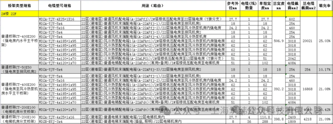
Based on all cable specifications derived from the load calculations and data such as cable outer diameters provided by suppliers, calculate the sum of the cross-sectional areas of all cables in each tray. At the request of the project owner's consultant, and to allow for later operational adjustments and reserved capacity, the fill ratio of power trays is rechecked to ensure it does not exceed 30%.
5) Illuminance verification method
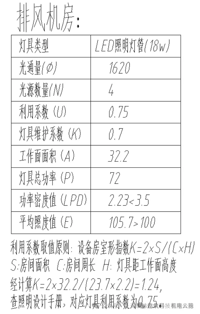
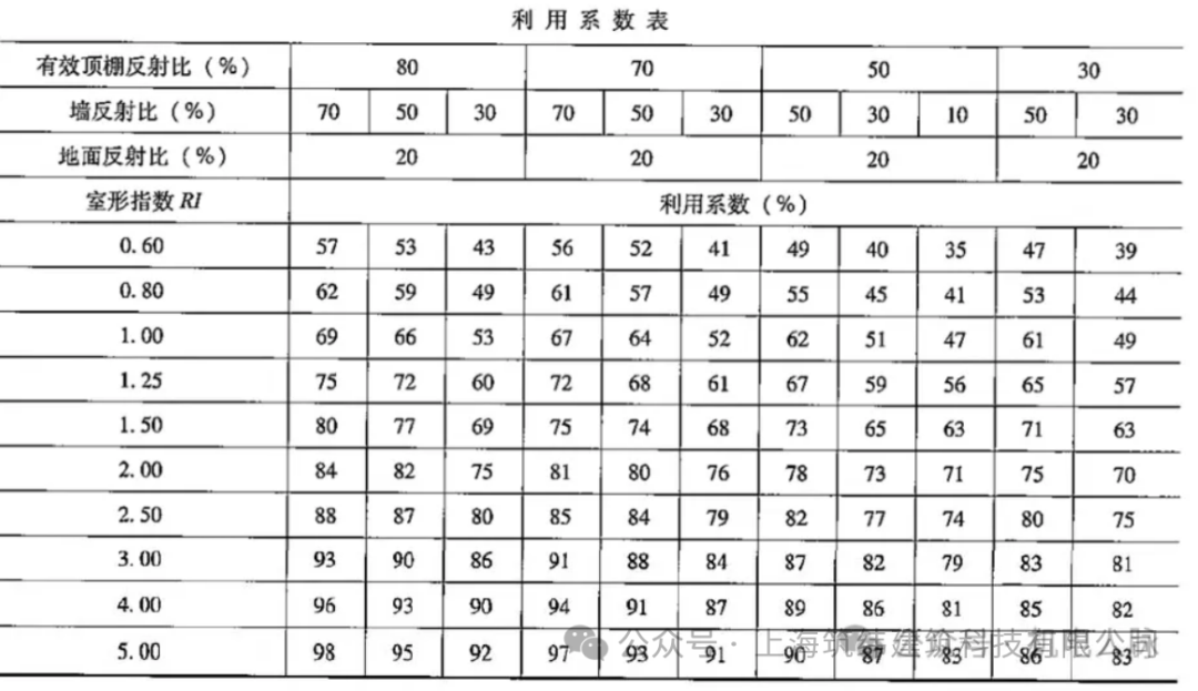
Based on the luminaire photometric parameters, luminous flux, and utilization factor tables provided by suppliers, the utilization factor method is used to calculate the power density and average illuminance for different functional areas, performing illuminance verification.
#2Comparison and selection of combined support design
The bases for support and hanger design selection and verification include the following codes and atlases:
1) 03S402 Indoor Pipeline Supports and Hangers
2) GB50242-2002 Code for Acceptance of Construction Quality of Building Water Supply and Drainage and Heating Engineering
3) 03K12 Duct Supports and Hangers
4) 03SR417-2 Installation Drawings for Prefabricated Pipeline Hanging
5) GB 50019-2015 Design Code for Heating, Ventilation and Air Conditioning of Industrial Buildings
6) GB50243-2016 Code for Acceptance of Construction Quality of Ventilation and Air Conditioning Engineering
7) G50303-2015 Code for Acceptance of Construction Quality of Building Electrical Engineering
8) 04D701-3 Cable Tray Installation
9) JGJ145-2013 Technical Specification for Post-Installed Anchors in Concrete Structures
10) GB50009-2012 Load Code for the Design of Building Structures
11) GB50017-2017 Standard for Design of Steel Structures
12) GB50981-2014 Code for Seismic Design of Building M&E Engineering
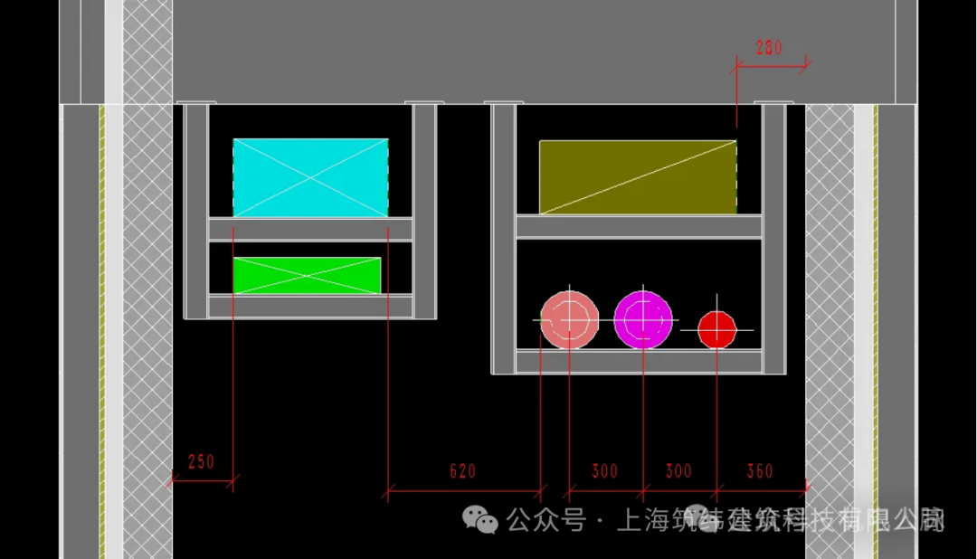
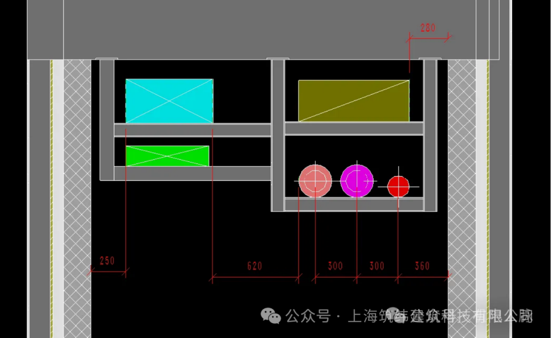
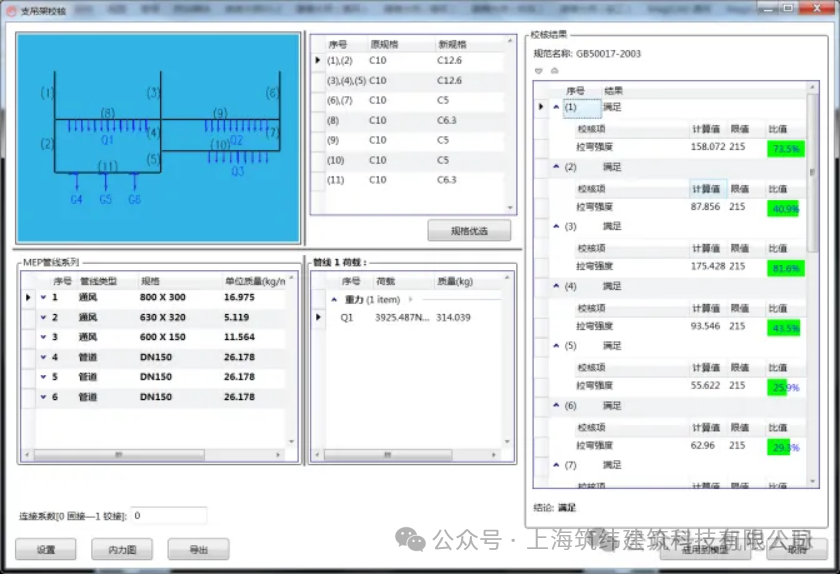
The differences are compared and the optimum is selected. In this example, Scheme 2 was ultimately chosen and automatically verified against the codes to ensure it meets the load-bearing requirements.
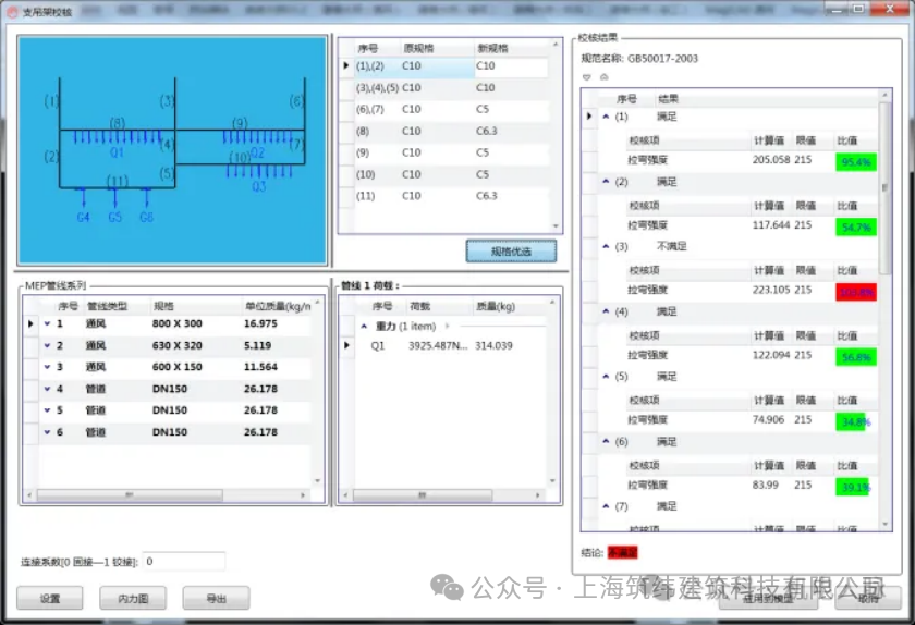
Scheme 1:
Scheme 2:
The preliminary design of the supports and hangers fails to meet the load-bearing requirements
After automatic verification by the software, the load-bearing requirements are met
#3Pipeline optimization design
In the detailed design phase, to optimize system performance, construction economy, and layout aesthetics, different layout schemes are compared, and the visualization and parametric features of BIM technology are used to intuitively select the optimal scheme.
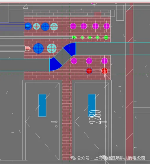
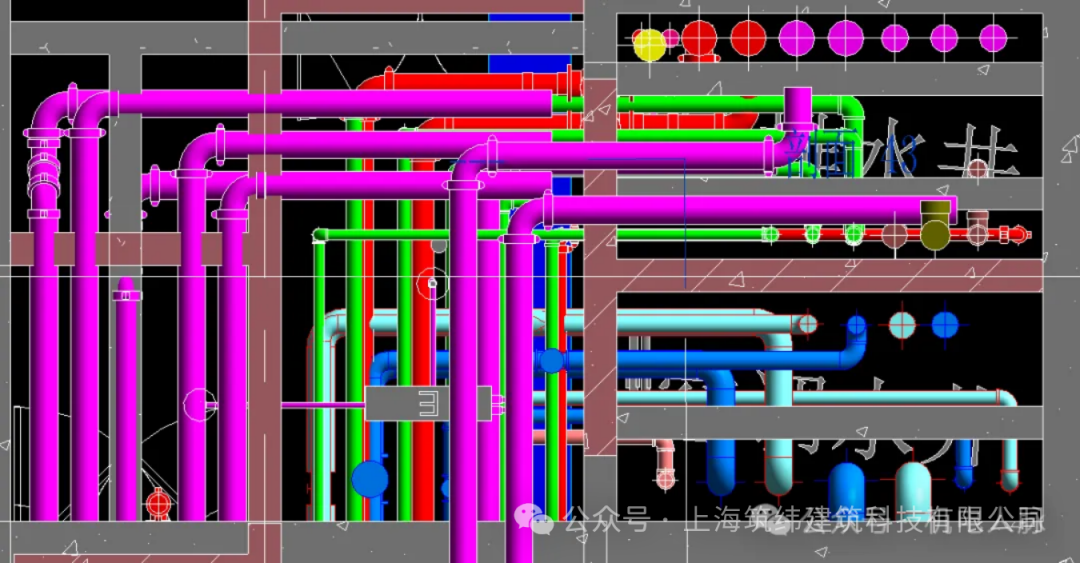
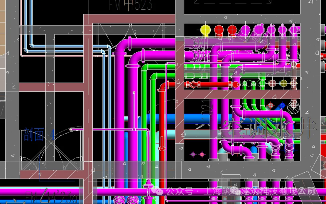
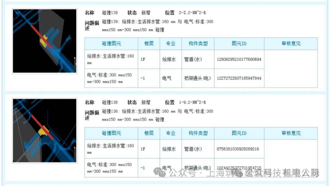
Clash reports are exported from the drawing review software to facilitate technical briefings.
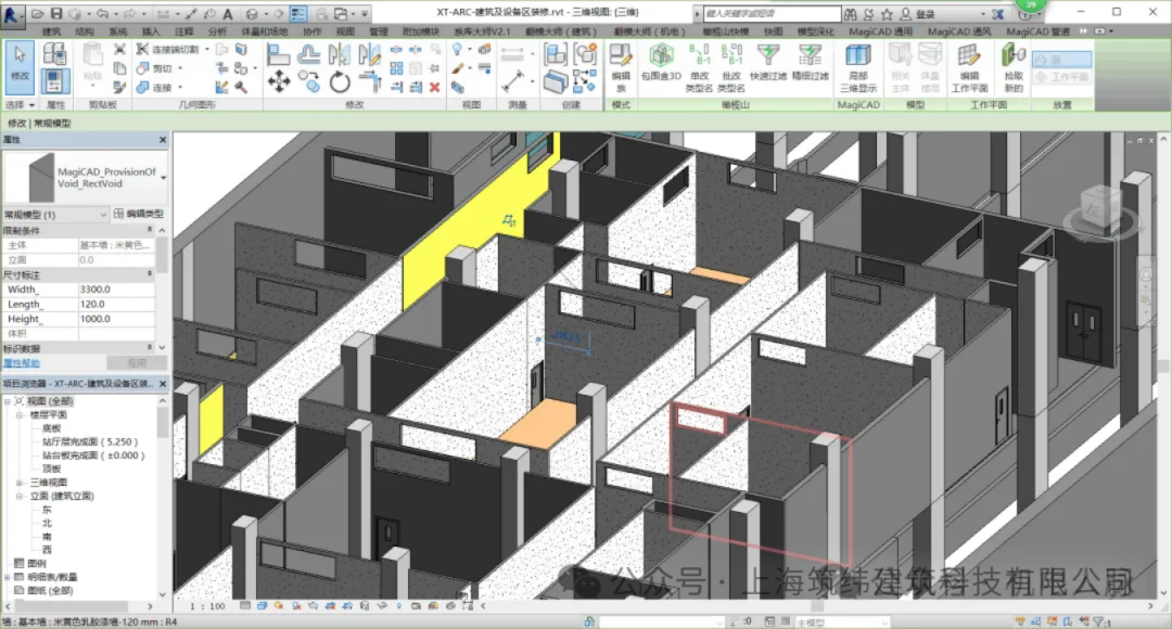
For BIM-based pre-embedding of wall-penetration sleeves: on the basis of the completed comprehensive detailed M&E model, Magicad software automatically reserves openings in walls and generates sleeves, and reserved-opening construction drawings are exported to guide construction setting-out.
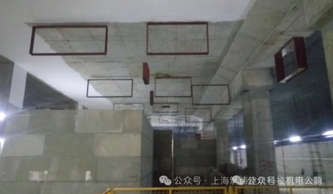
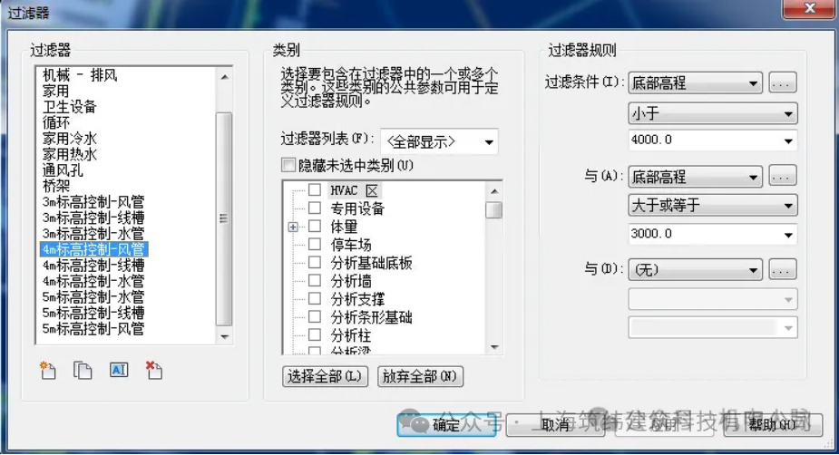
Adjusting the non-compliant locations at different elevations detected by the software greatly facilitates coordination with the fit-out work.The Fortune Center project had a floor height of 4.2m; through pipeline optimization, the standard floor height was ultimately and effectively controlled to 3.5m
END
The views expressed are the author's own Copyright © Zhuwei Architectural Technology
Reproduction without authorization is prohibited
Please credit the source when reposting: Zhuwei Architectural Technology
Zhuwei Architectural Technology is a new-type technical services company specializing in integrated design optimization, BIM consulting and prefabricated construction design consulting. Our team brings together senior engineers from leading design institutes, former executives of real-estate companies, BIM engineers and prefabrication engineers, delivering integrated design optimization, refined drawing review, BIM consulting with MEP detailing, and prefabricated design services.
Design optimization consulting: Positioned as an extension and complement to the design management of real-estate developers, we focus on consulting and optimization for civil buildings. Across the whole process — or at key stages required by the client — we control the economy, rationality and safety of the design, eliminating unnecessary cost while measurably improving drawing quality, achieving "lower cost, higher efficiency".
BIM consulting: Through digital construction technology we help designers reduce errors and improve quality in the design phase, help contractors save cost and plan high-quality MEP installation in the construction phase, and extend BIM models into facility management for the operation phase — in collaboration with mainstream software vendors.
Prefabricated design consulting: Whole-process design on BIM platforms, using Revit and Tekla for PC detailing. Component geometry and reinforcement are linked parametrically — what you see is what you get. We deliver Industry 4.0-ready drawings with cut-length data for every rebar, and IoT-enabled support for production, storage, transport and installation of PC components.
Our expert team comes from leading design institutes, with deep technical grounding and extensive experience in dual-track design and optimization; its technical capability and control are industry-leading.
—— This article is auto-synced from the WeChat Official Account “Zhuwei Architectural Technology”. Read the original ——