BIM Skills: Applying Parametric Technology to Precast Composite Floor Slabs
WeChat Sync · Xiaowei · 2023-09-13
The following article is sourced from: Engineering BIM Learning
[Abstract]:
After the structural calculation and analysis is completed, when drawing the construction drawings and fabrication drawings, the splitting and numbering of composite floor slabs currently still rely mainly on manual labor. During the splitting process, problems may arise such as large jumps in numbering and uneven split panels. At the same time, this tedious work takes up a great deal of the designer's time, leaving no time for more important design work. To improve the efficiency and accuracy of splitting, parameterization technology is introduced for partial research and application.
[Keywords]: Prefabricated construction, composite floor slab, parameterization
0 Introduction
The application of parameterization technology is becoming ever more widespread, but many people mistakenly believe that parameterization is only for irregular shapes, strange forms, curtain walls, and architectural concepts. In fact, these are only one area of its application, not all of it, and they do not conform to its underlying philosophy. In order to better combine it with prefabricated construction and bring its role into play, we here use a parametric approach to carry out the splitting, numbering, and tallying of composite floor slabs, and compare it with the traditional method to explore its application value in prefabricated buildings. The parts completed using parameterization this time are:
(1) Determination of one-way and two-way slabs
(2) Even splitting of panels
(3) Dimension annotation of split edges
(4) Numbering of panels by zone
(5) Annotation of the area and weight of split panels
(6) Tallying of the architectural wall loads on split panels
Among these, (1)(2)(3) belong to panel splitting, (3) belongs to panel numbering, and (5)(6) belong to panel tallying.
2 Project Overview
The Phase 1 of Plot 3 along Gongye Avenue South in Huadu District is located north of Kaiyuan Avenue and west of Yuyan Road in Huangpu District, Guangzhou. It is a supporting residential building project with a total site area of 25204 m² and a total floor area of 84738.6500m², of which 61041.82m² is above ground and 23696.83 m² is underground, with 33 floors above ground and 2 floors underground.
|
|
3 Application of Parameterization Technology for Splitting and Numbering Composite Floor Slabs
3.1 Determination of One-Way and Two-Way Slabs
In prefabricated buildings, the determination of one-way and two-way slabs is very important[1], as it affects the subsequent slab joints, reinforcement, installation, and so on; therefore, accurately determining one-way and two-way slabs is a very important matter. Here, the determination is made in accordance with Clause 9.1.1 of the Code for Design of Concrete Structures. For a normal quadrilateral slab, it can be easily determined once the two dimensions in the two directions are known; for slabs that differ in each direction, the program computes a bounding rectangle and makes the determination based on it. As shown in the figure below, the green part is the panel and the blue area is the bounding rectangle, and the determination uses the dimensions of the bounding rectangle. Judging from this application, no errors occurred in the determination.
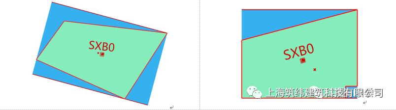
Determination of formwork direction
3.2 Even Splitting of Panels
After completing the splitting logic and extracting the slab contour lines, the 36 composite floor slabs on the first floor of Buildings C1 and C2 are split, and the splitting is completed within one minute. The splitting displays all even splitting methods for each panel within the set error range, draws out the contour lines of the split panels, and creates a new layer to hold the text of the splitting scheme. After the splitting method is later selected, deleting this layer or setting it as a non-printing layer will keep it from appearing in the final fabrication drawing. The result is as follows:
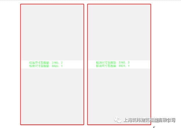
Splitting result
3.3 Dimension Annotation of Split Edges
The work in this part is completed simultaneously during the one-way/two-way slab determination. Its main purpose is to complete part of the dimension annotation, and it also allows the split panels to be checked. This dimension annotation is also managed on a newly created layer, which is convenient for batch operations.
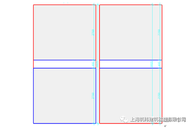
Dimension annotation of split edges
3.4 Numbering Split Panels by Zone
The zoning is mainly based on people's general reading habits, so that the numbering within each zone is continuous and does not jump. One only needs to box-select or click-select each zone to complete the numbering of that zone. When selecting the next zone for numbering, it builds on the last number of the previous zone. For example, if Zone 1 has 7 panels after splitting, numbered up to C1C2-PCB-7, then the selected Zone 2 will automatically start numbering from C1C2-PCB-8, and so on.
|
Dimension annotation of split edges |
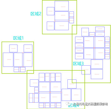
3.5 Annotation of the Area and Weight of Split Panels
In accordance with Appendix A of the Load Code for the Design of Building Structures, the unit weight of concrete is taken as 25KN/m³ for the weight tally. The panel area is tallied to facilitate subsequent work such as calculating the prefabrication rate. With the slab contour lines and slab thickness, the annotation can be completed quickly. The area and weight annotation here is again managed on a new layer[2].
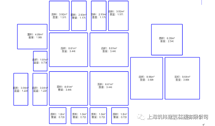
Annotation of panel area and weight
3.6 Tallying of Architectural Wall Loads on Split Panels
Using the panel contour lines and the 3D architectural walls, the volume of the architectural walls on a panel can be quickly extracted. The unit weight is determined in accordance with Appendix A of the Load Code for the Design of Building Structures or the design institute's unified technical measures, so that the wall area load on the panel can be quickly converted, as follows:
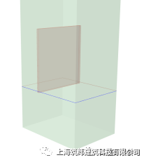
Compute the intersection of the solid extruded from the slab contour line with the 3D architectural wall
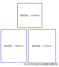
Iteratively compute the wall area load on the slab obtained from the intersection
4. Application Summary
4.1 Application Advantages
Using a parametric approach for splitting greatly improves work efficiency and makes the split panels very even. It displays all splitting schemes within a certain size range and a certain error, some of which may not be so easy for a person to think of on their own. Splitting, numbering, and tallying are all fairly tedious tasks; wherever the parametric part can be completed, efficiency is clearly improved. Below are two comparison charts: the curve represents the parametric approach and the straight line represents the traditional approach. When parametric splitting is used for the first time, the oa stage in the figure is the stage of observing patterns, forming the logic, and debugging; the output of this stage is 0, and once the logic is formed it is completed by the computer, which can produce output quickly. After the test is complete, the second time another project is encountered there is no oa stage; the curve can be moved directly to the origin and used directly, with very high efficiency.
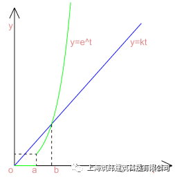
Efficiency comparison chart before the logic is formed
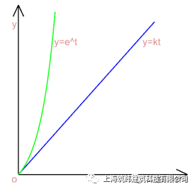
Efficiency comparison chart after the logic is formed
4.2 Application Drawbacks
Considering that in most actual cases the slab edges are supported, only the slab contour lines were extracted, without associating the slab's support conditions. During splitting, all slabs are assumed by default to be supported on four sides; for cases such as opposite-side support or cantilevers, which clearly belong to one-way slabs, the determination may be wrong. In the future, if such determination is genuinely needed, support elements such as beams can be loaded, and each edge of the slab can be checked for collision with the surrounding support elements, so as to meet the determination requirement.
4.3 Application Reflections
This application was divided into three parts—splitting, numbering, and tallying—and we did not choose to merge them into a single one-time generation. The reason is that structural design is a very rigorous task, and I hope that after each generation by the program, a person will check and verify it once, and only proceed to the next step when no problems are found. Compared with the traditional approach, where a person must both draw and check, the parametric approach requires a person to do only part of the operation and checking, and the time saved can be spent on more important design work. At the present stage, engineering software is becoming increasingly mature; it can be more closely combined with design or construction, selecting the parts where using BIM or parameterization offers a clear advantage for application, so as to improve accuracy and efficiency and leave more time to raise the design standard.
References: [1] Xie Zhongliang, Xu Yi, Zhang Qunli, Fang Bo, Gong Cong. Application of BIM parametric technology in the structural design of the canopy of the hockey venue for the Hangzhou Asian Games [J/OL]. Information Technology on Civil Architecture and Building Engineering
[2]Zhang Jilei, Qi Henghao. Application of BIM parametric technology in irregular-shaped buildings [J]. Jiangsu Building Materials, 2019(S1):52-54.
END
The views expressed are the author's own Copyright © Zhuwei Architectural Technology
Reproduction without authorization is prohibited
Please credit the source when reposting: Zhuwei Architectural Technology
Zhuwei Architectural Technology is a new-type technical services company specializing in integrated design optimization, BIM consulting and prefabricated construction design consulting. Our team brings together senior engineers from leading design institutes, former executives of real-estate companies, BIM engineers and prefabrication engineers, delivering integrated design optimization, refined drawing review, BIM consulting with MEP detailing, and prefabricated design services.
Design optimization consulting: Positioned as an extension and complement to the design management of real-estate developers, we focus on consulting and optimization for civil buildings. Across the whole process — or at key stages required by the client — we control the economy, rationality and safety of the design, eliminating unnecessary cost while measurably improving drawing quality, achieving "lower cost, higher efficiency".
BIM consulting: Through digital construction technology we help designers reduce errors and improve quality in the design phase, help contractors save cost and plan high-quality MEP installation in the construction phase, and extend BIM models into facility management for the operation phase — in collaboration with mainstream software vendors.
Prefabricated design consulting: Whole-process design on BIM platforms, using Revit and Tekla for PC detailing. Component geometry and reinforcement are linked parametrically — what you see is what you get. We deliver Industry 4.0-ready drawings with cut-length data for every rebar, and IoT-enabled support for production, storage, transport and installation of PC components.
Our expert team comes from leading design institutes, with deep technical grounding and extensive experience in dual-track design and optimization; its technical capability and control are industry-leading.
—— This article is auto-synced from the WeChat Official Account “Zhuwei Architectural Technology”. Read the original ——