Key Points for Reviewing Detailed Design Drawings of Precast (PC) Prefabricated Building Components
WeChat Sync · Xiaowei · 2023-12-22
This article is reprinted from the WeChat official account "N-Creation Design Knowledge & Practice Society" for learning and exchange purposes only. All rights belong to the original author.
The review and audit of PC component detailed design drawings for prefabricated buildings is one of the key steps to ensure the production quality of precast components and the safety of the project. By forming a professional review team to examine and evaluate the drawings from multiple perspectives - completeness, compliance, technical accuracy, safety and economy - the quality and reliability of the drawings can be effectively improved, laying a solid foundation for smooth construction and handover of the building. Below we set out in detail the key review points for the production drawings of detailed design for the various categories of precast components:
01 General Requirements for Drawing Review
1.1 The content of the title block shall be accurate and clear; information such as the project owner, project name, and design and review personnel shall be correct.
1.2 The drawing index shall include the sequence number, name, sheet size, remarks and other information of each component detail drawing, and the drawing sequence numbers shall be continuous; the names and numbers of each component detail drawing shall be consistent with the drawing index.
1.3 The precast component layout plan shall be annotated with information such as the component tag, positioning dimensions, component weight, lifting direction and the floor to which the precast component belongs, and shall correspond with each component detail drawing. Where necessary, the lifting sequence shall also be indicated.
1.4 The concrete strength grade of the precast component shall be stated in each component detail drawing.
1.5 The geometric dimensions of the precast component and the positions of the reinforcement and embedded items shall be accurately located; pay attention to whether the front/back face of each embedded item and the shape and length of each bar are correct.
1.6 On the drawings, each view shall be identified by name, and sectional views and cross-sections shall not be confused. The section symbol is "1┐" and the cross-section symbol is "1|"; they shall be used separately. Corresponding views shall be drawn in accordance with the applicable drafting rules.
1.7 Check whether the lifting capacity of the lifting accessories in the precast component meets the weight of the component. Lifting accessories shall be arranged symmetrically about the center of gravity and shall satisfy the corresponding detailing requirements. When a precast component has only two lifting points, anti-detachment measures shall be considered.
1.8 The specific specifications and properties of each embedded item shall be clearly defined, such as: (1) the exact dimensions of each embedded item; (2) whether metal embedded items require galvanizing; (3) whether the reinforcement used is seismic-grade; (4) the diameter of the wiring box hole and whether a raised type is used; (5) the material of the embedded items.
1.9 The positioning dimensions of the M&E reservations and embedded items in the precast component shall be consistent with the M&E construction drawings, and it shall be made clear whether the positioning dimensions are measured to the center of the embedded item or to its edge.
1.10 Embedded items in the precast component shall be accurately tagged, and different embedded items shall not be mixed up.
1.11 For precast components with openings, the arrangement of additional reinforcement and the quantity and specification of the bars shall be clearly annotated according to the size of the opening.
1.12 To facilitate demolding around openings, the side faces of the openings shall be given a taper along the demolding direction.
1.13 Check the concrete cover thickness of each component; it shall not be less than the minimum cover for the corresponding component. When the concrete cover to the longitudinal reinforcement in beams and columns exceeds 40 mm, effective crack-control detailing measures shall be taken for the cover.
1.14 Check whether the drawing notes are reasonable and fluent, whether the technical terms and units of measurement comply with national standards, and whether there are any typographical errors.
02 Composite Slab Review Guidelines
2.1 Identify the floor slab type: full-precast slab, hollow-core slab, prestressed composite slab or lattice composite slab.
2.2 Where the composite slab is non-rectangular or interferes with components such as frame columns, check whether notches have been provided; the dimensions of the notches shall be clearly annotated.
2.3 Where the composite slab is stepped down, check whether its positional relationship with the surrounding components has taken production and construction tolerances into account.
2.4 Cross-check with the structural construction drawings; the load-bearing direction and the load-transfer mechanism shown in the drawing shall be consistent, and it shall be clearly identified as a one-way or two-way slab.
2.5 Cross-check with the layout plan to confirm whether the lifting direction in the precast slab detail is consistent with that shown on the layout plan.
2.6 Check whether the composite slab has any over-width or over-length issue: slab width shall not exceed 3.0 m (including projecting bars), and slab length shall not exceed 5.0 m.
2.7 Check whether the bearing lengths on the load-bearing edge and the non-load-bearing edge of the composite slab are correct, and whether they have been considered in the component mold drawing.
2.8 Verify whether information such as the concrete strength grade of the slab, the reinforcement grade, quantity, diameter and length is correct and consistent with the structural construction drawings, and whether the distribution bars meet the minimum reinforcement ratio requirement.
2.9 If prestressing tendons are placed in the slab, check whether the tendon diameter, spacing, jacking control factor and concrete cover to the prestressing tendons have been clearly annotated.
2.10 Where no lattice reinforcement is provided in the slab, check whether shear-transfer bars (horse-shape bars) are installed between the precast bottom slab of the composite slab and the cast-in-situ topping concrete, and whether the extent of the shear-transfer bars complies with the code. The height of the horse-shape bars shall not interfere with the top reinforcement layout and shall ensure that the concrete cover to the top reinforcement meets the requirements.
2.11 For lattice composite slabs, the height and spacing of the steel lattice, the diameters of the individual bars and whether the bottom chord serves as load-bearing reinforcement shall all be stated. The lattice height must be selected on the basis of calculations that take into account the slab thickness, concrete cover thickness and reinforcement layer thickness.
2.12 The top/bottom positions of the load-bearing and distribution reinforcement in the lattice composite slab shall be consistent with the structural construction drawings.
2.13 Different bar shapes shall be tagged separately; there shall be no mis-tagging, omission or duplication of tags.
2.14 Check whether the projecting lengths of the bars on the different faces are correct and whether they will affect the lifting of the component.
2.15 Check whether the concrete cover to the reinforcement in the drawing meets the relevant code requirements; pay particular attention to whether the cover to the prestressing reinforcement meets the required fire-resistance rating of the building.
2.16 Where precast hollow-core slabs are used, check whether detailing measures for sealing the voids have been provided.
2.17 The number of lifting anchors shall meet the lifting weight requirement of the precast slab, and their spacing and locations shall satisfy the corresponding detailing requirements. For lattice composite slabs, the lifting points shall be located at the intersections of the lattice web members and the top chord bars.
2.18 Check whether the dimensions and locations of embedded items and reserved openings (plumbing, electrical, etc.) in the precast slab are consistent with the requirements of the related disciplines, and whether reinforcement is provided around the reserved openings. When the side dimension of the opening is not greater than 300 mm, the additional reinforcement shall comply with the national standard atlas Lattice Reinforced Concrete Composite Slab (60 mm Thick Bottom Slab) 15G366-1; when the side dimension of the opening exceeds 300 mm, additional reinforcement shall be provided in accordance with clause 7.2.6 of 16G101 Rules for Drawing Structural Construction of Concrete Structures and Detail Drawings, or by reference to the Handbook of Concrete Structural Detailing.
2.19 The positioning dimensions of M&E reservations and embedded items in the precast slab shall be consistent with the M&E construction drawings, and it shall be clearly stated whether the dimensions are measured to the center of the embedded item or to its edge.
2.20 Check whether the drawing has made provision for survey holes, material-handover holes and the like, and whether their dimensions and additional reinforcement are annotated.
2.21 Check whether the drawing has made provision for embedded items for construction equipment such as cantilevered working platforms, and whether their dimensions and additional reinforcement are annotated.
2.22 Check whether the side faces and top face of the precast slab have been roughened in accordance with the code requirements.
2.23 Check whether the M&E reservations and embedded items in the precast slab are fully annotated and whether the property information of the embedded items is given.
2.24 Check whether the reinforcement layout within the composite slab interferes with the plumbing and electrical embedded items.
2.25 Additional reinforcement shall be provided within the composite slab beneath beamless partition walls, with the bar specification, spacing and type clearly annotated.
2.26 In a lattice composite slab, the bottom chord of the lattice shall be used as load-bearing reinforcement to reduce steel tonnage. Within the range permitted by the code, the lattice reinforcement shall, wherever possible, overlap with the original load-bearing bars so as to reduce the quantity of the original bars.
2.27 For fully precast balconies (including fully precast beams), the projecting bars shall avoid interference with the stirrups of the supporting component so as to ensure that lifting remains feasible.
2.28 The projecting bar length of fully precast balconies (including fully precast beams) shall meet the atlas requirements.

03 Composite Beam Review Guidelines
3.1 Check whether the dimensional annotations of the component are complete and correct; cross-check with the architectural and structural construction drawings to determine whether flanges or upstands are required to facilitate the installation of adjacent components and to meet waterproofing requirements.
3.2 Based on the slab thickness and the heights of the various frame beams, verify whether the height of the precast layer of the composite beam is correct. Check whether the bearing length of the component is uniform and reasonable and whether it interferes with other adjacent components at the support.
3.3 The reinforcement in the precast beam detail shall be consistent with the structural construction drawings; check whether "E"-marked (seismic-grade) reinforcement is used.
3.4 Check whether the extent of the stirrup confinement zone of the precast frame beam has been annotated, and whether the length of the confinement zone satisfies the relevant code requirements.
3.5 Different bar shapes shall be tagged separately; there shall be no mis-tagging, omission or duplication of tags.
3.6 The anchorage length of the bars at the beam end shall meet the code requirements; check whether the projecting bar length interferes with the longitudinal bars of the supporting component.
3.7 To avoid bar interference, bars may be bent and set out to bypass the reinforcement of adjacent components; the dimensional annotations shall be complete.
3.8 Check whether the dimensions and detailing of the embedded items, notches and the like at the junction of main and secondary beams are clearly expressed in the drawing.
3.9 At the junction of main and secondary beams, the stirrups of the main beam shall be densified or additional hanger bars provided, and the bar-bending detail shall be supplemented.
3.10 Check whether the roughened surface and shear keys at the interface between the precast beam and the cast-in-situ topping concrete, grout or bedding mortar meet the relevant code requirements.
3.11 Check whether the number of lifting anchors is sufficient for the lifting weight of the precast beam (especially for industrial plants with heavy loads), and whether their positions satisfy the corresponding detailing requirements.
3.12 Check whether the dimensions and locations of the embedded items and reserved openings in the composite beam are consistent with the requirements of the related disciplines, and whether additional reinforcement is provided around the reserved openings.
3.13 Where the composite beam is precast separately from the precast wall, check whether the joint location for vertical ducts passing through the composite beam lies within the thickness of the wall beneath the beam.
3.14 The longitudinal bars projecting from the end of the composite beam shall have their length annotated and be accurately located; where anchorage plates are used, the type shall be stated.
3.15 The length of torsional reinforcement extending into the support shall meet the anchorage length requirement.
3.16 The cross-sectional dimensions and reinforcement information of the precast beam shall be consistent with the structural construction drawings; check whether the straight length of the stirrup hook satisfies the atlas requirement (10d, 75).
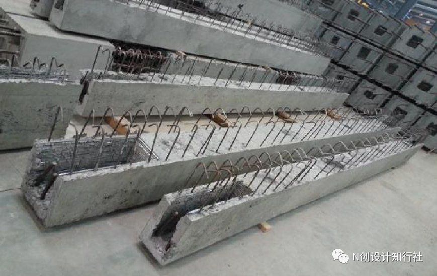
04 Precast Column Review Guidelines
4.1 Where the longitudinal bars of the beams spliced to a precast column are bent downwards, the height of the precast column shall take the bar bend length into account.
4.2 Check whether the reinforcement in the precast column shop drawing is consistent with the structural drawings, and whether "E"-marked (seismic-grade) reinforcement is required.
4.3 The drawing shall accurately locate the grout sleeves, indicate the horizontal projection positions of each grout inlet and outlet hole, and provide an operability plan.
4.4 The bottom of the frame column shall be provided with shear keys and vent holes; the key depth should not be less than 30 mm, and the top of the column shall be roughened.
4.5 Check whether the extent of the confinement zone at the grout sleeve locations of the frame column meets the code requirements. The stirrup confinement zone of a column shall be the largest of the column cross-sectional height, 1/6 of the clear column height and 500 mm; at the bottom of ground-floor columns it shall be not less than 1/3 of the clear column height.
4.6 Check whether the concrete cover to the reinforcement at the relevant locations in the precast column shop drawing meets the code requirements, particularly at the grout sleeve connection locations.
4.7 Check whether the number of lifting anchors is sufficient for the lifting weight of the precast column, and whether the positions of the lifting anchors satisfy the corresponding detailing requirements.
4.8 Where the topmost column is cast in situ, check whether the length of the projecting bars from the precast column below satisfies the lap-splice or connection requirements.
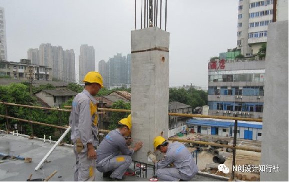
05 Precast Wall Review Guidelines
5.1 Check whether a rebate (tongue-and-groove joint) is provided at the horizontal joints of the precast external wall, and whether a rebate is provided at the connection between the bottom of the ground-floor precast external wall and the cast-in-situ layer.
5.2 Check whether the external-wall insulation or facing tiles are embedded at the factory; if they are to be bonded on site, the outer face of the wall shall be roughened.
5.3 Check whether the positions, spacing and edge distances of the insulation connectors inside the precast wall satisfy the design requirements and are clearly annotated.
5.4 The structural floor level shall be annotated on the wall elevation view.
5.5 Check whether the wall height is correct. The wall height shall take the slab thickness into account, and particular attention shall be given to how variations in the cast-in-situ topping thickness affect the height of the precast wall.
5.6 Check whether the window-sill height in the precast external wall has taken the thicknesses of the architectural finish and floor insulation layers into account.
5.7 Check whether waterproofing measures have been provided at the window openings in the precast external wall, such as stepped upstands, falls and drip lines.
5.8 Check whether provision has been made at the top of the topmost precast shear wall for a cast-in-situ ring beam (not less than 250 mm).
5.9 Check whether tie-bar holes have been reserved or couplers embedded on the side of the precast wall adjacent to a cast-in-situ wall.
5.10 Check whether couplers have been embedded on the side of the precast wall adjacent to another precast wall.
5.11 Check whether the precast external wall has reserved the entry position of the construction hoist as required by the construction plan.
5.12 The precast external wall shall have embedded connectors at the tower-crane tie-in positions and construction-hoist anchorage positions in accordance with the construction requirements.
5.13 Check whether embedded items have been provided at the anchorage positions of the diagonal braces on the precast external wall as required by the construction plan.
5.14 Check whether the precast external wall, once installed, will obstruct the horizontal tie-in arms of the tower crane.
5.15 Check whether the concrete cover to the reinforcement in the precast wall meets the relevant code requirements and whether the concrete grade has been stated.
5.16 Check whether the reinforcement ratio of the precast wall (not less than 0.15% for non-load-bearing walls) meets the requirements, and whether the additional reinforcement around the openings satisfies the requirements. Check also whether the additional horizontal reinforcement at the base of the precast shear wall complies with the code.
5.17 Check whether tie bars are provided in the precast wall and meet the requirements (arranged in a rectangular or staggered pattern with a spacing of no more than 600 mm).
5.18 Check whether the projecting bar lengths of the precast wall meet the design requirements; the dimensional annotations in the drawing shall be complete and accurate.
5.19 The wall casting-bed dimensions are 3.5 x 9 m and 4.0 x 12 m; the corresponding wall dimensions shall not exceed 3.15 x 8 m and 3.65 x 11 m respectively.
5.20 Sub-frames or window-frame connectors shall be embedded at the window openings as required; check whether the specifications and positions of the sub-frames and connectors have been stated.
5.21 Preservative-treated timber battens shall be embedded at the door openings in the precast wall as required; check whether the dimensions and layout of the battens have been stated.
5.22 The dimensions and locations of the embedded items and reserved openings in the precast wall shall be consistent with the requirements of the related disciplines.
5.23 The connections between the precast wall and the main structure shall be safe and reliable; in particular, cladding wall panels shall be designed with movable connections. Check whether each connection satisfies the anti-corrosion, fire-resistance and water-tightness requirements.
5.24 Where the precast wall is connected to the main structure by connectors, check whether the connectors are correctly located and whether the detail drawings are complete.
5.25 Check whether the number of lifting anchors, lifting bars and other lifting accessories is sufficient for the lifting weight of the precast wall; they shall be arranged symmetrically about the center of gravity, and their positions shall satisfy the corresponding detailing requirements.
5.26 Where the openings in the precast wall are large, additional steel supports shall be provided for temporary reinforcement and shall be annotated with leader notes.
5.27 Check whether an equipotential bonding box has been embedded in the wall at bathroom locations; the connection to the slab reinforcement shall be considered.
5.28 The inner face of the wall at bathroom locations shall be roughened to facilitate the bonding of wall tiles and the like.
5.29 Check whether a cast-in-situ upstand has been considered around the base of the wall at bathroom locations, and whether the reduced-slab level has been considered at the top.
5.30 Check whether the precast internal partition wall has been weight-reduced, and whether the connection measures with the surrounding components are safe and reliable.
5.31 Where distribution boxes are embedded in the precast wall, check the number of conduit entries at the top and bottom.
5.32 When making reservations and embedments in a precast wall, the distance between the architectural finished surface and the bottom of the component shall meet the requirements.
5.33 The positioning dimensions of the M&E reservations and embedded items in the precast wall shall be consistent with the M&E construction drawings; it shall be clearly stated whether the dimensions are measured to the center of the embedded item or to its edge.
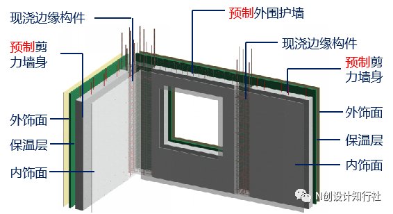
06 Precast Staircase Review Guidelines
6.1 Identify the staircase type - Type A, B, C or D - and specify whether the support is a sliding bearing or a fixed bearing.
6.2 Where a sliding bearing is used for the precast staircase, check whether its rotational and sliding deformation capacity meets the relevant code and atlas requirements.
6.3 The going and rise of every step of the stair flight shall be dimensioned, and the outline of every step shall be consistent with the architectural drawings.
6.4 For scissor stairs, the construction method of the partition wall shall be clearly defined; the partition wall shall not be placed on the precast stair flight, which would affect its sliding.
6.5 Openings at the supports shall be provided with additional reinforcement in accordance with the atlas and code requirements.
6.6 Check whether the connection between the precast staircase and the balustrade/handrail is safe and reliable, and whether the connectors need to be embedded.
6.7 On the basis of the architectural construction drawings, determine whether the precast staircase is to have a finish layer, whether anti-slip nosings are to be provided, and the specific detailing of the anti-slip nosings.
6.8 Lifting anchors shall be arranged on both the top and the side faces of the stair flight. Check whether the number of lifting anchors is sufficient for the lifting weight of the precast staircase, and whether their positions satisfy the corresponding detailing requirements.
6.9 The top reinforcement of the stair flight shall be continuous.
6.10 When the stair landing beams are precast, only half of the top landing beam corbel needs to be precast; the half without the corbel shall be precast with an upstand.
6.11 The staircase layout plan shall show the connection details at both the upper and lower supports and shall list the quantities of the components.
6.12 Check whether the first or last step differs in rise from the other steps owing to the finish-layer thickness at the landing.
6.13 Check whether the slab thickness at the bearing locations of the precast staircase (excluding the bedding mortar layer) is consistent with the structural construction drawings.
6.14 For the corbels at the supports of the precast stair landing beams, the reinforcement shall satisfy the anchorage requirements and the cross-section shall satisfy the shear and flexural requirements.
6.15 The cross-sectional dimensions and reinforcement information of the precast stair landing beam shall be consistent with the structural construction drawings; check whether the straight length of the stirrup hook satisfies the atlas requirement (10d, 75).
Conclusion
When reviewing the production drawings of detailed design for the various categories of precast components, an integrated assessment shall be made in light of the actual production conditions and construction environment. At the same time, the reviewers shall fully communicate and coordinate the views of all parties to ensure drawing quality and construction safety. Through a scientific and rigorous drawing review, the production quality of precast components can be effectively improved, construction risks can be reduced, and strong support can be provided for the sustainable development of prefabricated building.

Author: Zhang Xianchao, Senior Engineer and Chief Technology Officer, who has long been engaged in the design and consulting management of building engineering.
END
The views expressed are the author's own Copyright © Zhuwei Architectural Technology
Reproduction without authorization is prohibited
Please credit the source when reposting: Zhuwei Architectural Technology
Zhuwei Architectural Technology is a new-type technical services company specializing in integrated design optimization, BIM consulting and prefabricated construction design consulting. Our team brings together senior engineers from leading design institutes, former executives of real-estate companies, BIM engineers and prefabrication engineers, delivering integrated design optimization, refined drawing review, BIM consulting with MEP detailing, and prefabricated design services.
Design optimization consulting: Positioned as an extension and complement to the design management of real-estate developers, we focus on consulting and optimization for civil buildings. Across the whole process — or at key stages required by the client — we control the economy, rationality and safety of the design, eliminating unnecessary cost while measurably improving drawing quality, achieving "lower cost, higher efficiency".
BIM consulting: Through digital construction technology we help designers reduce errors and improve quality in the design phase, help contractors save cost and plan high-quality MEP installation in the construction phase, and extend BIM models into facility management for the operation phase — in collaboration with mainstream software vendors.
Prefabricated design consulting: Whole-process design on BIM platforms, using Revit and Tekla for PC detailing. Component geometry and reinforcement are linked parametrically — what you see is what you get. We deliver Industry 4.0-ready drawings with cut-length data for every rebar, and IoT-enabled support for production, storage, transport and installation of PC components.
Our expert team comes from leading design institutes, with deep technical grounding and extensive experience in dual-track design and optimization; its technical capability and control are industry-leading.
—— This article is auto-synced from the WeChat Official Account “Zhuwei Architectural Technology”. Read the original ——