Precautions for Prefabricated Construction
WeChat Sync · Xiaowei · 2023-10-26
The following article is sourced from: Doudin Construction
01 Site acceptance of precast components
1) After all components arrive on site, they shall be accepted one by one in accordance with the specification, covering appearance quality, geometric dimensions, embedded parts, reserved holes, etc.; any nonconformity found shall be handled;
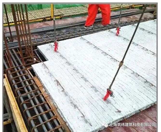
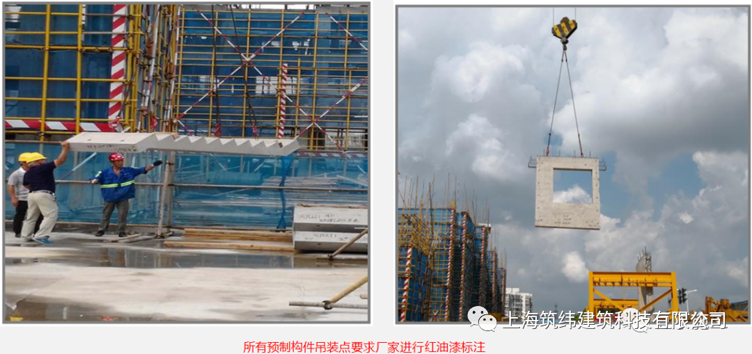
2) For all precast components without lifting rings, the manufacturer shall be required to mark the lifting points with red paint; after delivery to site, it shall be checked whether the lifting points have been marked
02 Lifting methods for precast components
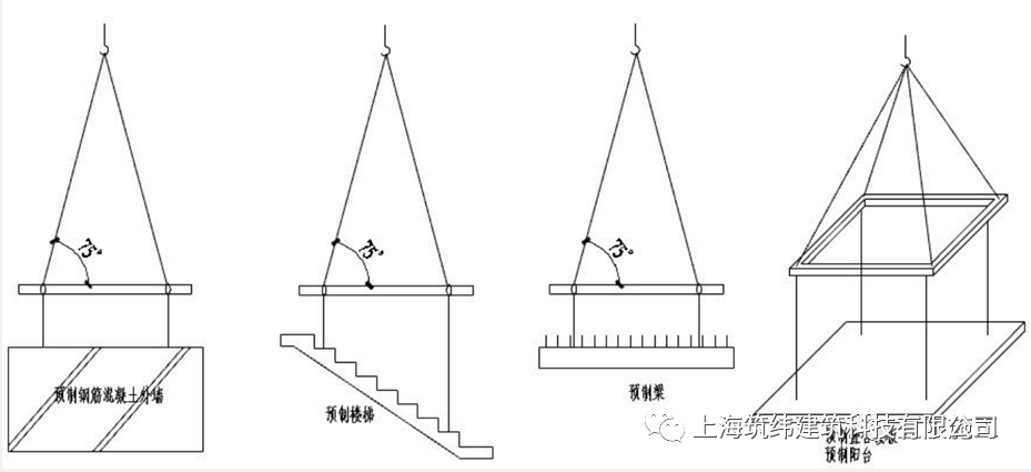
1) When the design has no special requirements, PC lifting must use a section-steel lifting beam (as shown in the figure);
2) The suspension positions shall be the designed lifting points; the designed lifting points shall not be adjusted or omitted;
03 Positioning measures for connection rebars of vertical precast walls
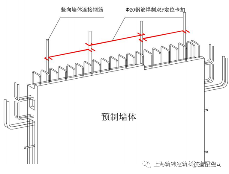
1) Use welded rebar double-F positioning clips (as shown in the right figure) to check and correct the vertical connection rebars, so that the precast wall can smoothly align with the connection rebars;
2) Install the double-F positioning clips before the initial setting of the concrete, and recheck the position of the vertical rebars;
3) Before installing vertical components, a secondary check shall be performed; any misalignment shall be adjusted as specified in the code, and cutting rebars is strictly prohibited;
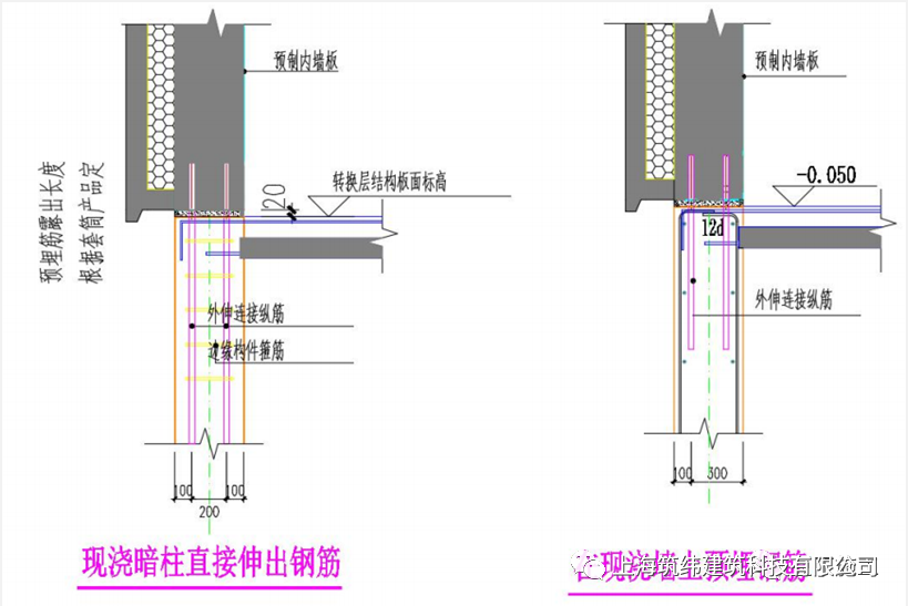
04 Transition dowel bars between the cast-in-situ layer and the prefabricated layer
1) Check whether the diameter of the vertical longitudinal rebars of the cast-in-situ wall matches that of the projecting connection longitudinal rebars; if they match, use the reserved rebars in Figure 1, and if they do not, use the embedded rebars in Figure 2;
2) The positioning of the projecting connection longitudinal rebars shall match the sleeve positions of the precast wall panels;
3) The positioning of the embedded rebars shall be accurate, and their positions shall be checked according to the requirements of Article 6;
05 Grouting of vertical wall connections (compartment division)
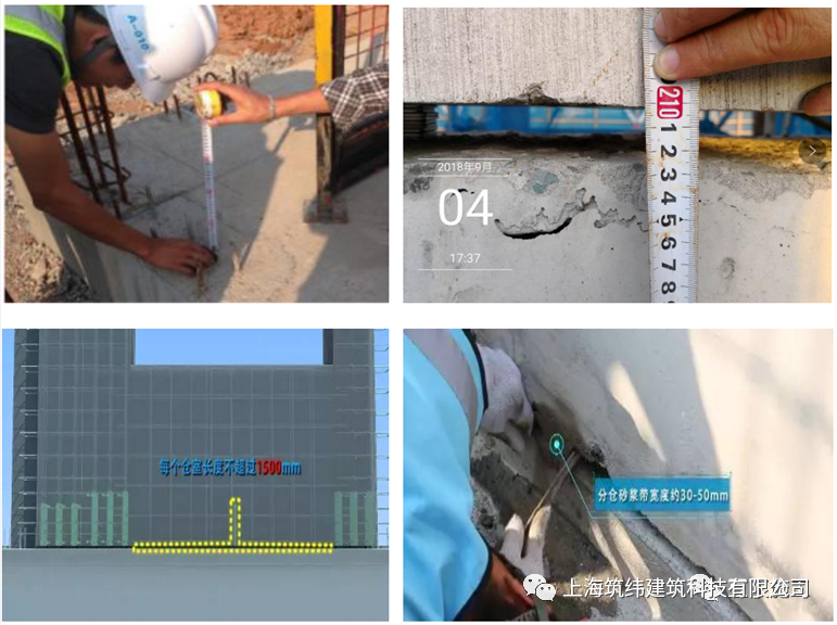
1) Level the precast wall panel by padding its four bottom corners; when installing the shims, care shall be taken to avoid blocking the grout inlet holes and the connected grouting cavities;
2) After the precast wall is lifted into position and adjusted, carry out the bedding-mortar compartment division and sealing; when the connected-cavity grouting method is used, each connected grouting zone (compartment length) should not exceed 1500mm, and the compartment mortar strip shall be 30-50mm wide;
06 Grouting of vertical wall connections (compartment sealing)
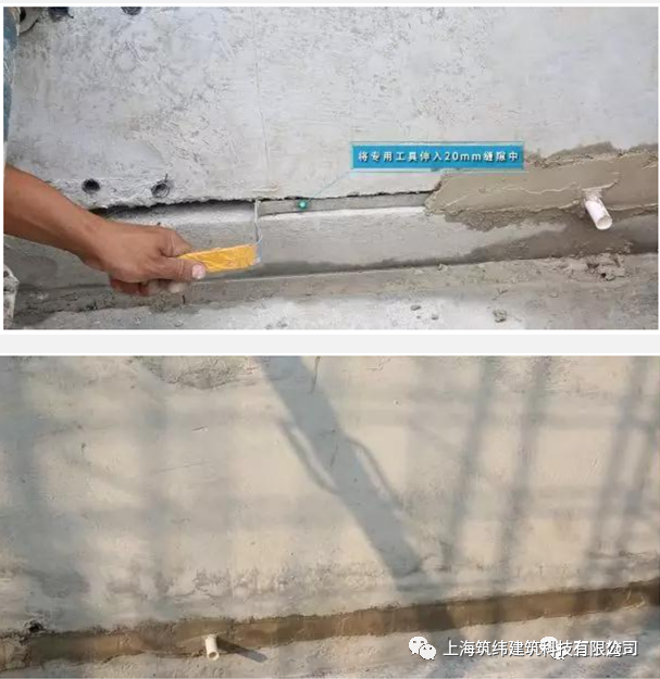
1) Compartment sealing uses a dedicated tool inserted 20mm into the gap to serve as a backing strip for troweling the sealing mortar.
2) Trowel the sealing mortar while withdrawing the backing strip, until completion;
3) The sealing quality of the sealing mortar shall meet the grouting requirements;
07 Grouting of vertical wall connections (grouting)
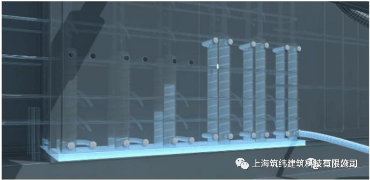
1) The grouting of vertical components must be supervised on site by project management personnel;
2) During grouting, ensure that the grout outlet holes can discharge grout smoothly;
3) Before grouting, the grout volume shall be calculated, and the actual grout volume must meet the requirement;
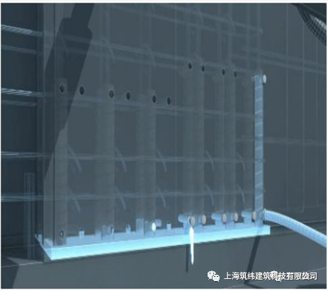
08 Grouting steps:
1) The grout mixture is pressurized from the grouting cylinder through the conduit and flows into the cavity and sleeve via the grout inlet hole;
2) When the grout mixture flows out of the other grout holes and outlets of the component without bubbles, promptly seal them with rubber plugs.
09 Grouting of vertical wall connections (grout leakage treatment)
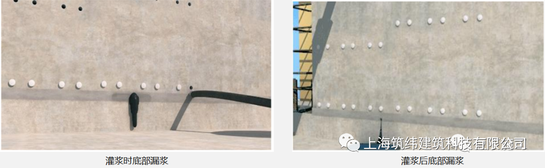
1) Treatment of grout leakage during grouting: stop grouting and treat the leaking area. In case of severe leakage, the precast wall panel must be lifted and the compartment resealed;
2) Treatment of grout leakage after grouting: carry out secondary supplementary grouting at a pressure slightly lower than the initial grouting pressure, and open the outlet hole near the leaking area during the supplementary grouting. Select the grout hole closest to the leaking area for grouting, seal it once the grout flows out without bubbles, and proceed in sequence;
10 Grouting of vertical wall connections (no-grout-discharge treatment)
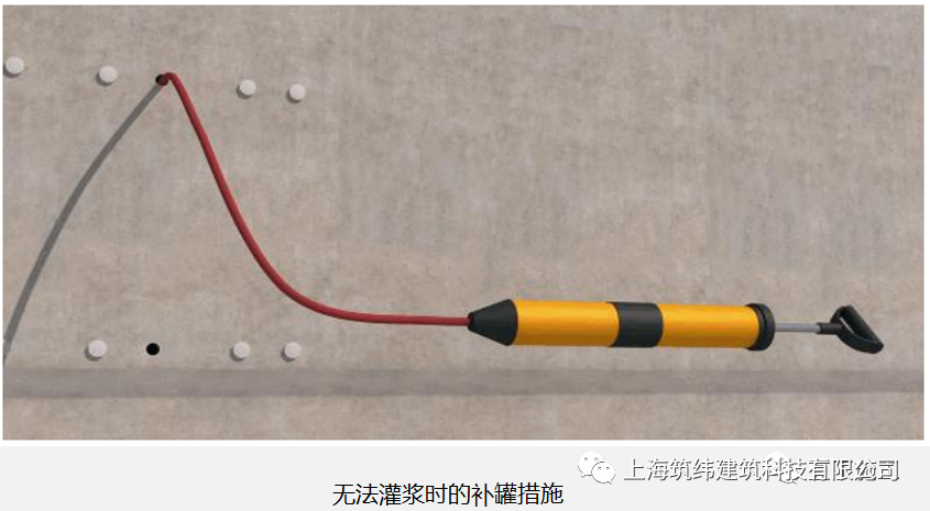
1) Within 30 minutes from when water is added and the grout is mixed, supplementary grouting can be done at the grout hole;
2) When the grout can no longer flow, supplementary grouting can be done from the outlet hole, using manual equipment combined with a fine pipe to grout through the outlet hole.
11 Connection bolts between precast walls and cast-in-situ walls
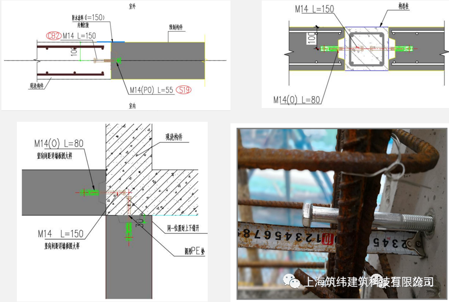
1) The tightening torque of the connection bolts between precast walls and cast-in-situ walls shall comply with the requirements of JGJ107-2016;
2) The project shall define exposed-bolt markings at each node according to the design requirements to facilitate inspection.
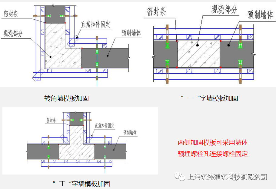
12 Formwork details at intersections of precast walls
1) Precast walls shall have reserved through-wall bolt holes for formwork reinforcement;
2) The number and spacing of the reserved through-wall bolt holes for formwork reinforcement shall meet the formwork reinforcement needs of the cast-in-situ walls;
3) Attach sealing strips along the edges of the precast walls to prevent grout leakage.
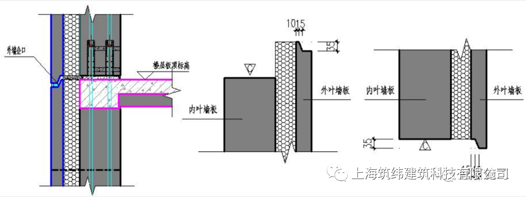
13Water-stop rebate details for precast exterior wall panel components
1) A rebate is provided on the outer side of the precast exterior wall panel to reduce rainwater penetrating indoors along the joints;
2) The rebate style shown is only an example and not the only option; each project may set the rebate style according to the actual project conditions;
3) The rebate details are proposed during detailed design.
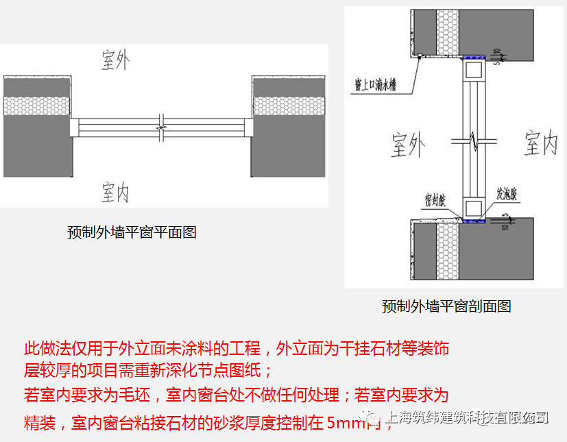
14 Rebate provided at flat window openings in precast walls
1) During detailed design of the precast exterior wall drawings, a rebate is added around the window opening to prevent rainwater from penetrating indoors;
2) The horizontal installation position of the exterior window is determined by the actual project conditions; the section in the figure is illustrative;
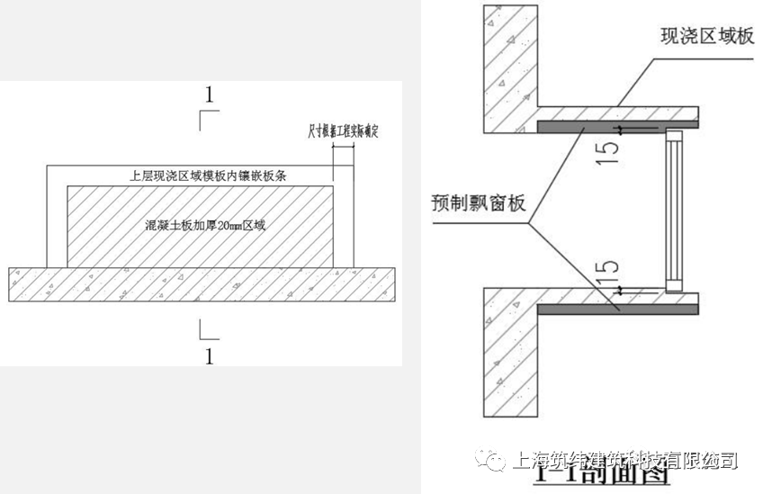
15 Rebate provided on precast bay-window slabs
1) During detailed design of the precast bay-window slab drawings, a rebate is added to the upper and lower bay slabs to prevent rainwater from penetrating indoors;
2) The horizontal installation position of the exterior window is determined by the actual project conditions; the section in the figure is illustrative.
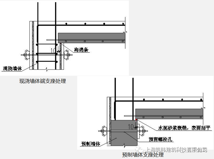
16 Grout-leakage prevention measures at composite slab end supports
1) Cast-in-situ shear wall: attach a continuous sponge strip to the top of the wall formwork to prevent grout leakage at the connection;
2) Precast shear wall: reserve through-wall formwork bolt holes at the top of the wall, and fix the external formwork using the through-wall holes. The joint between the wall and the composite slab is caulked with cement mortar and the surface is scraped flat.
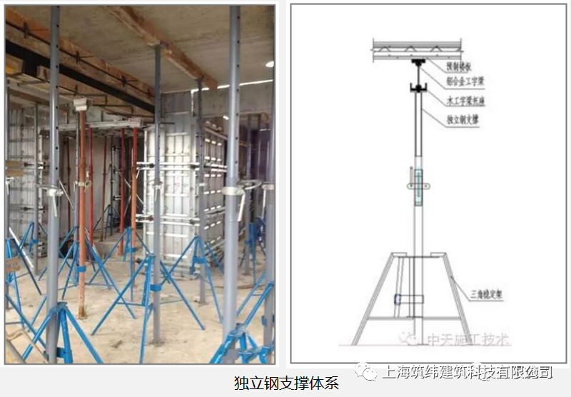
17Composite slab support system (independent supports)
1) A cross beam (10*10 timber batten or metal cross beam) is set at the top of each independent steel support;
2) The spacing between cross beams shall not exceed 1.8m. The distance from a cross beam to the wall shall not exceed 0.5m;
3) The spacing of independent supports along the cross-beam direction shall not exceed 2.0m, and the distance to the wall shall not exceed 0.5m;
4) Direction of the support cross beam: perpendicular to the long side of the composite slab; for two-way slabs, perpendicular to the cast-in-situ slab strip;
5) The formwork erection for cast-in-situ floor slabs is considered separately.
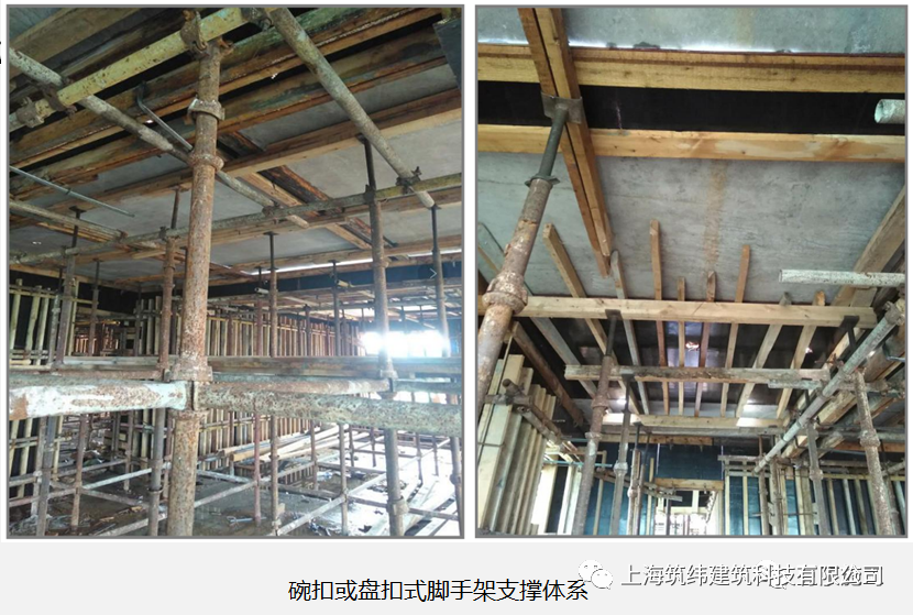
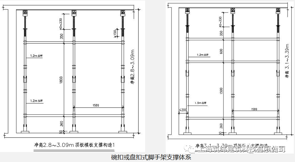
18Composite slab support system (non-independent supports)
1) When using cup-lock or ring-lock scaffold systems, connect them in the middle with horizontal bars, at a distance of no more than 0.5m from the wall;
2) The longitudinal and transverse spacing of vertical posts shall not exceed 1.5m, and the free-end height of the support shall not exceed 650mm; when the floor height does not exceed 3.1m, two horizontal bars may be provided;
3) The primary joists use square steel tubes or 100*100 timber battens;
4) The layout of the joists is considered together with the formwork of the cast-in-situ floor slab.
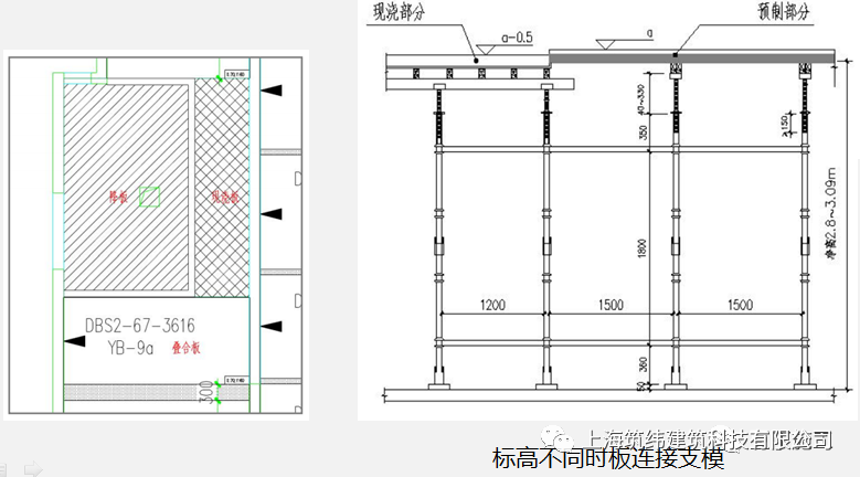
19 Formwork for the connection between composite slabs and cast-in-situ slabs
1) When the composite slab and the cast-in-situ slab are at the same level, use the formwork system shown in Figure 1;
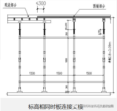
2) When the cast-in-situ slab is dropped and the levels differ, use the support method shown in Figure 2.
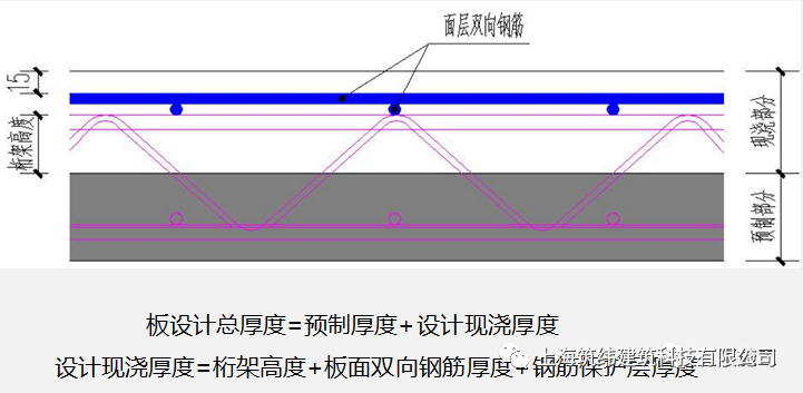
20 Tying of top rebars on composite slabs
1) During detailed design of the cast-in-situ topping thickness, it must be considered whether the total thickness still meets the rebar cover requirement after the surface rebars are tied;
2) The reinforcement of the upper cast-in-situ slab of the composite slab shall be tightly tied to the truss rebars (especially at the root of the shear wall) to prevent the rebars from springing up and becoming exposed;
3) The slab surface rebars should be designed to be tied on top of the truss rather than threaded through the truss and tied underneath (which is too difficult to construct).
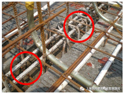
21 Handling of the intersection between composite slab installation and beam main rebars
The reserved rebars at the ends of the composite slab intersect with the main rebars of the coupling beams of the walls at both ends. During construction, the beam main rebars are tied first, their positions are adjusted before installing the composite slab, and the beam main rebars are tied again after the composite slab is installed.
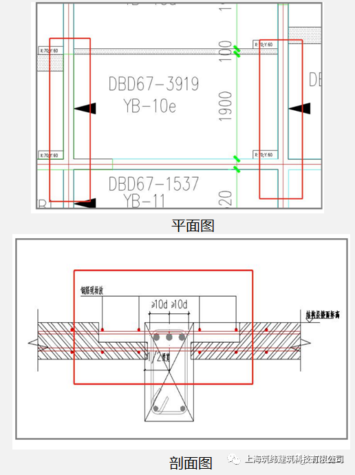
22 Cast-in-situ strip joint details for composite slabs
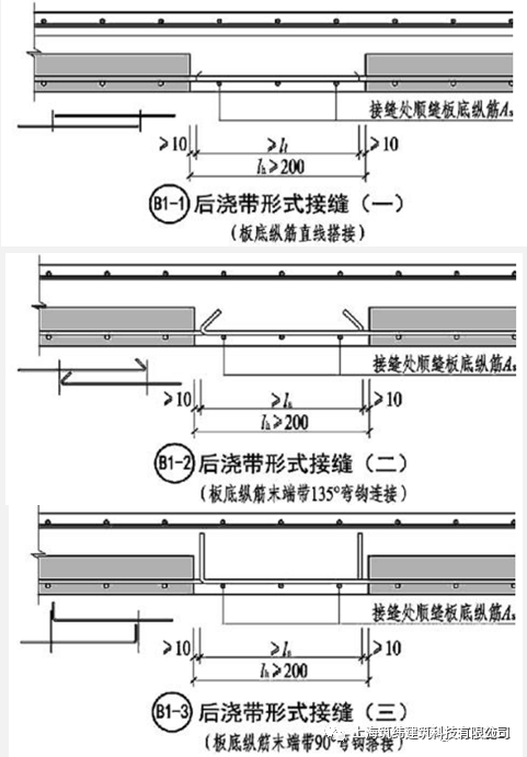
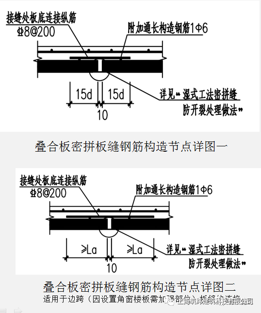
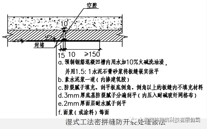
1) For the cast-in-situ strip joint of two-way slabs, the specific rebar connection method may adopt one of the three types shown in the right figure, with the actual choice determined by the design;
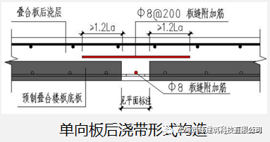
2) For one-way slabs designed with a cast-in-situ strip joint, additional joint reinforcement shall be added at the joint;
3) When casting the cast-in-situ strip of the composite slab, vibration must be thorough to ensure connection quality.
23 Connection methods for precast stairs
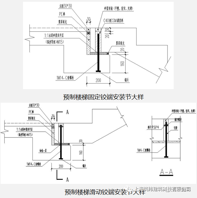
1) The levels shall be carefully verified before installing precast stair slabs;
2) The upper connection of the precast stair slab is a fixed hinge bearing and the bottom is a sliding hinge bearing; (selected from 15G367-1)
3) The grout holes of the fixed hinge bearing shall be well protected before grouting to prevent debris from entering the ducts; during grouting, the compactness of the grout shall be strictly controlled;
24 Level control for precast stairs
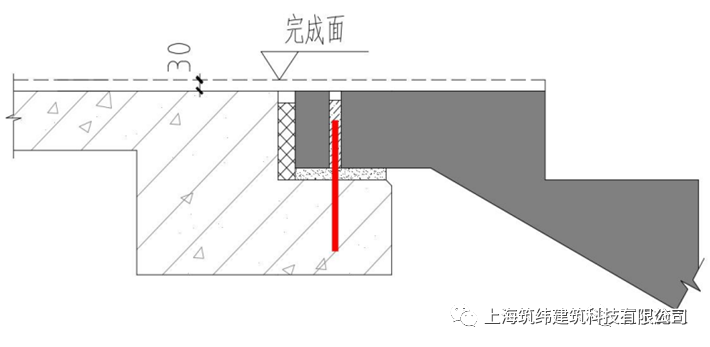
1) The level of the precast stair landing surface shall be consistent with the finished structural level of the cast-in-situ stair beam,
2) leaving 30mm at the surface layer for plastering or tiling.
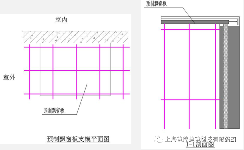
25 Formwork scheme for precast bay-window slabs and balcony slabs
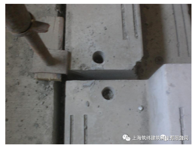
1) A dedicated formwork scheme shall be prepared for the construction of precast bay-window slabs and balcony slabs;
2) The supports of all cantilevered precast components may only be removed after the cast-in-situ concrete at the connections reaches the design strength;
26 Grouting of vertical wall connections (no-grout-discharge treatment)
27 Conduit laying methods for composite slabs
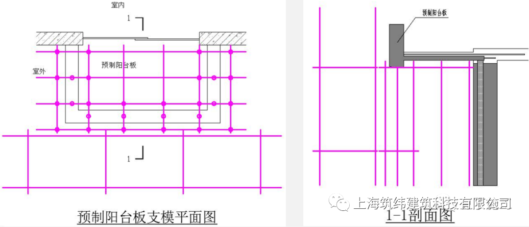
1) When the conduit diameter for pipeline laying exceeds the clear spacing inside the truss and the conduit cannot pass through the truss, the following methods can be adopted:
(1) Use a tool to slightly lift the truss rebar at the conduit-passing location;
(2) Cut the truss rebar at the conduit-passing location and then perform double-sided lap welding; (this method requires communication and confirmation with the designer)
(3) If the above two methods affect the cover thickness of the top rebars, implement Method 3.
2) Before laying water and electrical pipelines, the routes shall be optimized in advance to avoid pipeline crossings as far as possible.
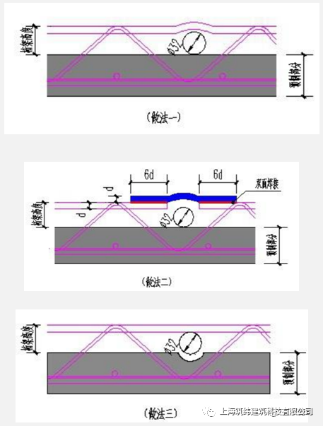
28 Reserved 30-type junction boxes and embedded sleeves for composite slabs
1) The reserved positions of junction boxes on top of the composite slab shall be communicated and confirmed in advance, especially for fine-decoration projects, to avoid later drilling;
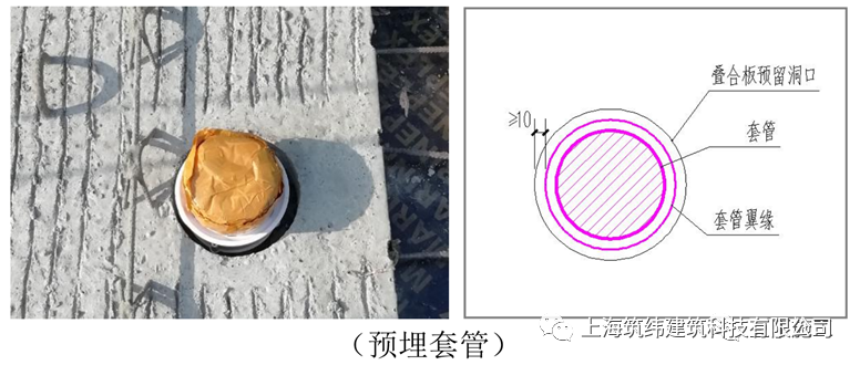
2) For composite slabs, the radius of the embedded drainage water-stop sleeve opening = wing-ring radius + 10mm;
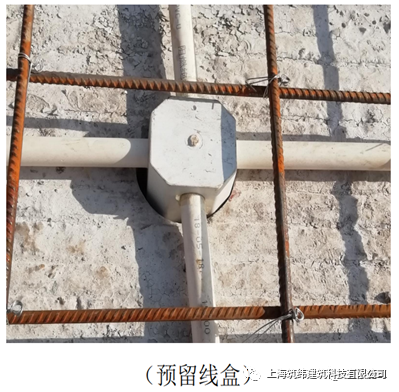
29 Reserved openings for pump pipes
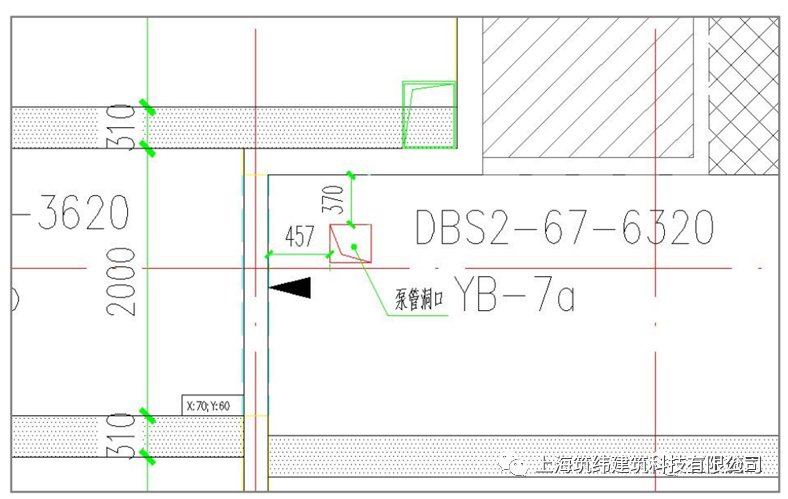
1) Before construction, the construction scheme shall be developed from the detailed design of the drawings, and the concrete pump-pipe opening positions shall be reasonably arranged in advance; the composite slab manufacturer reserves the openings according to the scheme, and later drilling is not allowed;
2) The construction scheme shall specify the size and exact positioning of the reserved concrete pump-pipe openings, rather than roughly indicating their approximate location.
30Reserved holes for external scaffolding and cantilevered I-beam embedded parts
1) The detailed design of the drawings shall consider the erection of external construction scaffolding, specify the scaffold type and its specific installation and use methods, and ensure the scaffolding meets the project's own needs;
2) Cantilevered I-beams require embedded anchors and reserved openings; determine the positions and quantities of the I-beam anchor embedments and the positions and quantities of the holes passing through the exterior wall;
3) The positions of the cantilevered wall ties shall be clearly defined; the wall-tie members set in precast components shall be embedded.
END
The views expressed are the author's own Copyright © Zhuwei Architectural Technology
Reproduction without authorization is prohibited
Please credit the source when reposting: Zhuwei Architectural Technology
Zhuwei Architectural Technology is a new-type technical services company specializing in integrated design optimization, BIM consulting and prefabricated construction design consulting. Our team brings together senior engineers from leading design institutes, former executives of real-estate companies, BIM engineers and prefabrication engineers, delivering integrated design optimization, refined drawing review, BIM consulting with MEP detailing, and prefabricated design services.
Design optimization consulting: Positioned as an extension and complement to the design management of real-estate developers, we focus on consulting and optimization for civil buildings. Across the whole process — or at key stages required by the client — we control the economy, rationality and safety of the design, eliminating unnecessary cost while measurably improving drawing quality, achieving "lower cost, higher efficiency".
BIM consulting: Through digital construction technology we help designers reduce errors and improve quality in the design phase, help contractors save cost and plan high-quality MEP installation in the construction phase, and extend BIM models into facility management for the operation phase — in collaboration with mainstream software vendors.
Prefabricated design consulting: Whole-process design on BIM platforms, using Revit and Tekla for PC detailing. Component geometry and reinforcement are linked parametrically — what you see is what you get. We deliver Industry 4.0-ready drawings with cut-length data for every rebar, and IoT-enabled support for production, storage, transport and installation of PC components.
Our expert team comes from leading design institutes, with deep technical grounding and extensive experience in dual-track design and optimization; its technical capability and control are industry-leading.
—— This article is auto-synced from the WeChat Official Account “Zhuwei Architectural Technology”. Read the original ——