Comprehensive Application of BIM Technology in the Construction of a Hospital Project
WeChat Sync · Xiaowei · 2024-12-02
The following article is sourced from Engineering Digital BIM Drafting
01
Key Difficulties and Preparatory Work of This Project
• Key Project Difficulties:
Adjacent to a River and the Sea, with Abundant Water:The east side of this project is about 50 meters from the Wanquan River, the groundwater level is relatively high (-3.71 m), and the bottom elevation of the foundation-mat cushion is -7.2 m. After completion, the basement will remain in a water-rich environment for a long time, so foundation-pit dewatering and basement waterproofing are the key concerns.
Coordinated Control of Prefabricated Components:The prefabrication rate of this project exceeds 50%. The mold division and layout of its precast components, reservations and embedded parts, multi-discipline coordinated detailed design, as well as production-schedule control and transportation-and-installation organization, are the focus of the project's coordinated management.
Unique Curved Curtain-Wall Design:The irregular curved curtain wall places high demands on the accurate positioning of pre-installed embedded parts. Ensuring that the arc-shaped curved facade is smooth and fluid is a key point and difficulty of this project's construction.
Multi-Discipline Coordinated Detailed Design:Coordinated detailed design across multiple disciplines—main structure, secondary structure, M&E engineering, curtain-wall engineering, and interior fit-out engineering—to reduce quality-control risks, avoid rework, and improve construction efficiency is a key focus.
Multi-Party Coordination and Organizational Management:Hospital projects are highly specialized, involve many disciplines, have a broad scope of cross-operation, and entail high coordination and organization costs across disciplines. Defining interfaces among disciplines, coordinating collaboration, and reasonably organizing and coordinating all participating parties are key factors in ensuring the smooth construction of the project.
• Software Collaboration
This project implements BIM technology. The relevant software used is as follows:
|
|
| Revit: main BIM modeling | Magicad: M&E pipeline coordination and support-and-hanger calculation |
|
|
| Glodon construction BIM software: site layout, tile arrangement, scaffolding detailed design, etc. | Tekla: steel-structure detailed design |
|
|
| Navisworks: model lightweighting and clash detection | Lumion: rendering, scene walkthrough animation, etc. |
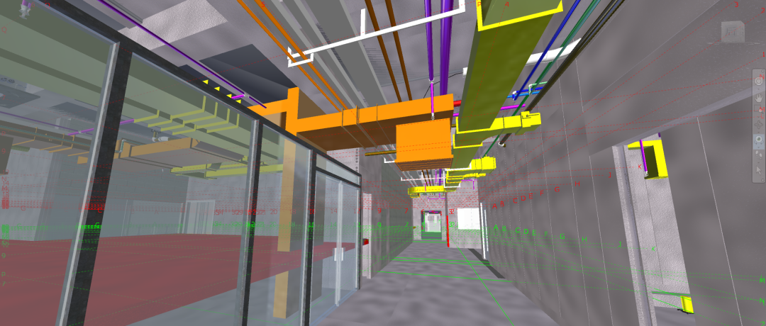
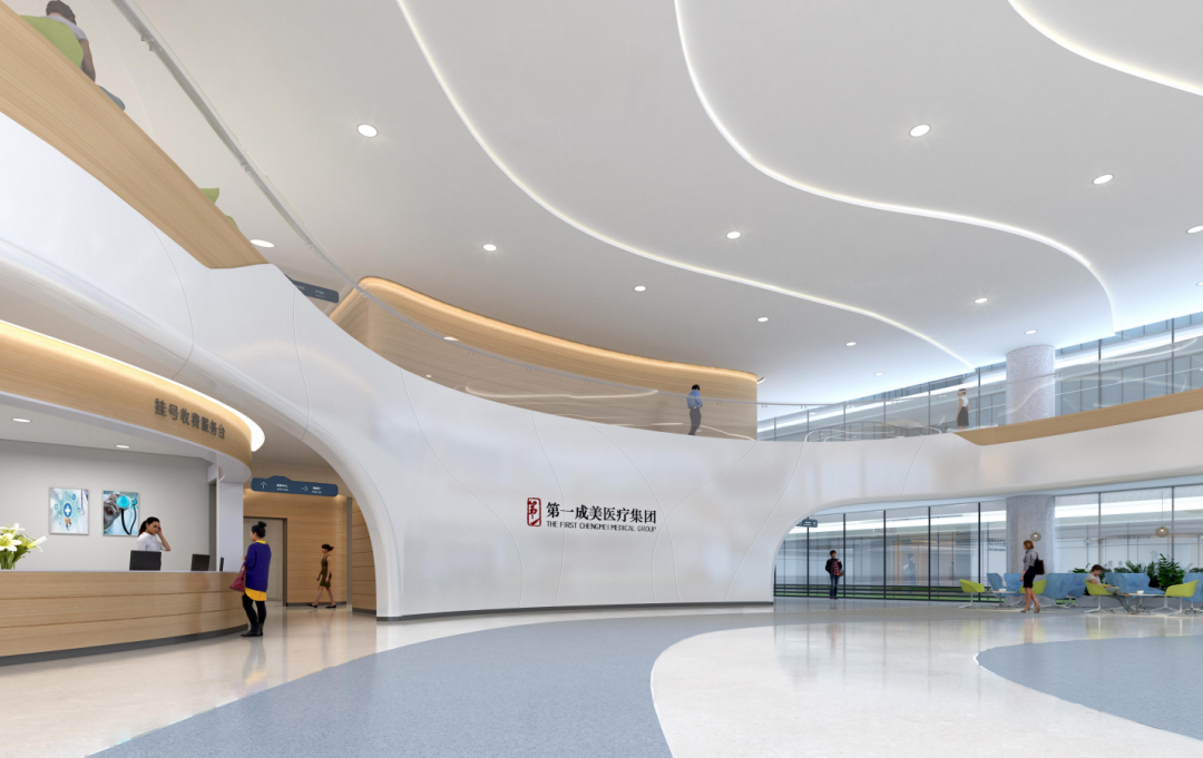
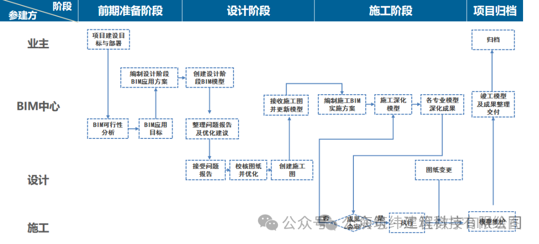
• Overall BIM Technology Route
02
BIM Technology Application Points
• Drawing Joint Review
By building the BIM model, the construction drawings were checked and construction problems were resolved in advance. To date, a total of 7 sets of change drawings have been issued, including 4 versions of construction drawings and 3 versions of interior fit-out drawings; a cumulative total of 246 problem reports have been produced, including 184 civil-engineering problems and 62 M&E problems.
Examples:
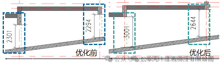
At the 1# garage ramp entrance, the distance from the beam bottom to the ramp slab is too small, affecting normal use. Through three-dimensional spatial design, it is recommended to upstand the two beams here so that the beam bottoms are flush with the slab bottom.
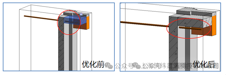
The drainage outfall elevation is -1.5 m, the floor-slab elevation is -1.2 m, and the slab thickness is 0.4 m, so the reserved sleeve overlaps with the roof slab. Based on the outdoor pipe-network elevation, the drainage-pipe sleeve elevation is lowered to 200 mm below the slab bottom to avoid a clash between the pipe and the floor slab.
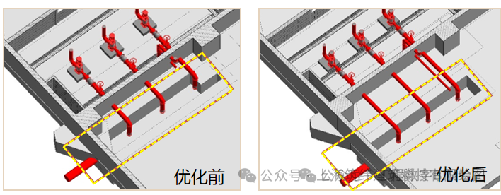
The suction pit inside the basement fire-water tank and the fire outfall pipe clash with the pile cap. Through coordinated optimization, the suction pit and fire pipe are moved down by 1,600 mm to avoid the clash.
• Key Points of Site Layout
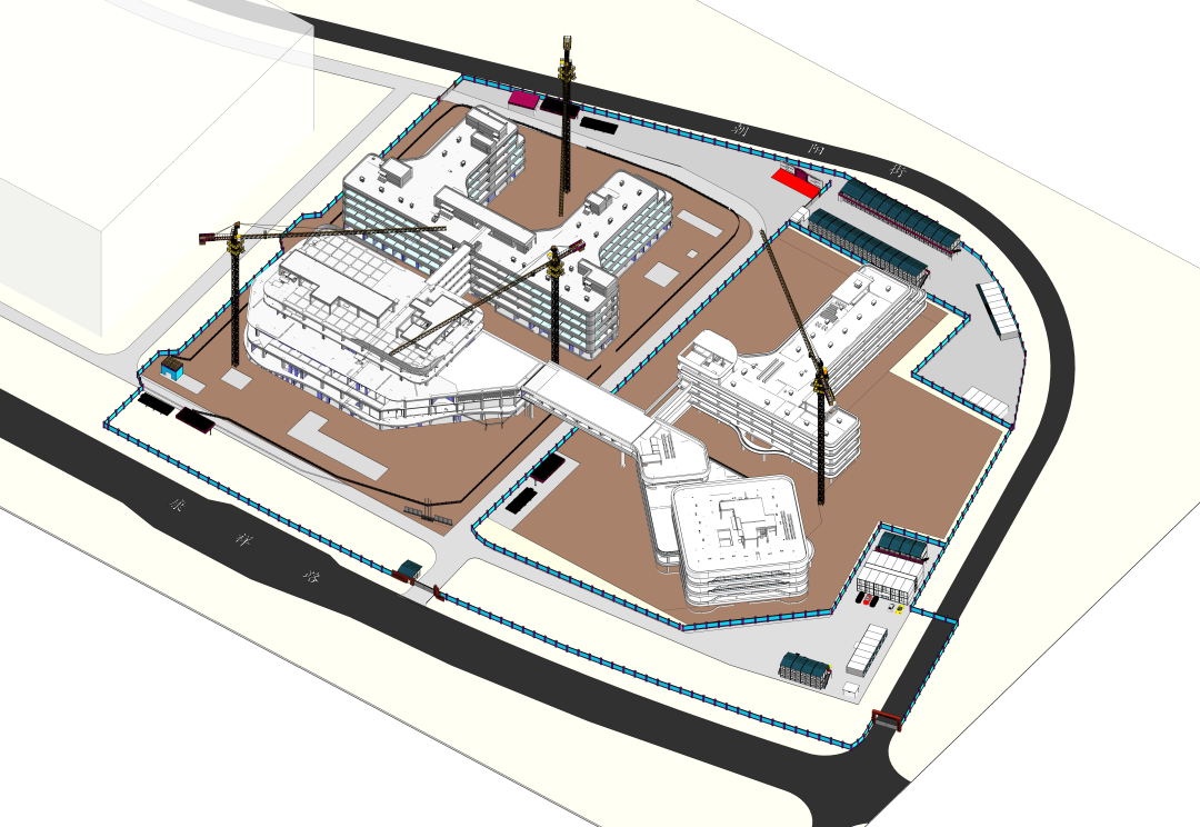
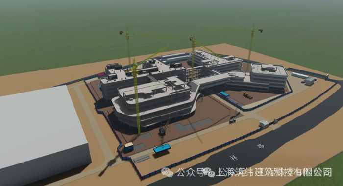
(1) The ring road is 4.5 m wide; there are 2 entrances and exits; the clear width of the fire lane is greater than 4 m;
(2) Analyze hazard sources and set up edge-protection railings;
(3) Set up raw-material storage, rebar processing, and finished-rebar storage to reduce secondary handling;
(4) Position distribution boxes to reduce the length of temporary-power cables;
• Detailed Design of Auxiliary Schemes
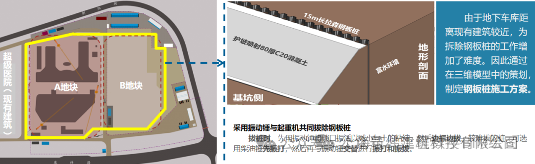
1. The project's foundation is a sandy soil layer, adjacent to a river and the sea (the closest distance to the Wanquan River is about 75 meters), with abundant water. The groundwater-level elevation is 0.79 to 1.59 m (relative elevation -6.41 to -7.21 m). The foundation-pit dewatering design scheme adopts one row of Larsen steel sheet piles around the pit for water-blocking support, plus a φ500 large-diameter ultra-deep pipe-well dewatering structure, achieving the dewatering goal through two measures. BIM technology is used for visual simulation to assist construction.
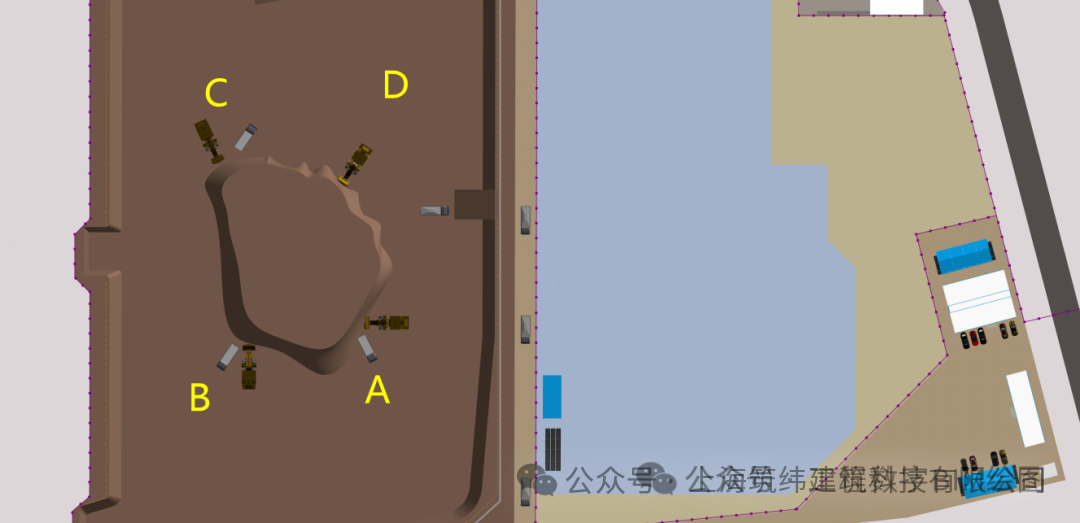
2.All temporary roads in this project are set as 8-meter-wide dual lanes. To ensure the orderly progress of construction processes on site, a reasonable underground-garage earthwork excavation scheme is formulated. To improve construction efficiency, the garage is divided into four blocks—A, B, C, and D—excavated from the edges toward the center, and during the underground construction phase the post-cast strip method is used to construct the blocks in a staggered sequence of A, C, B, D.
3. To meet construction needs, three 7020 flat-head tower cranes are arranged on site to achieve 100% coverage. This greatly improves tower-crane transport efficiency, and anti-collision equipment is added to the tower cranes to ensure safe construction. The tower-crane spray linkage device effectively controls on-site dust.
• Pile-Length Statistics
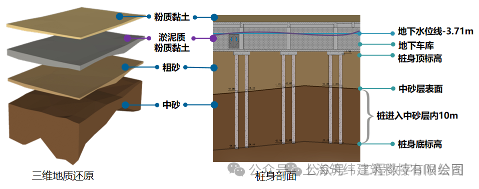
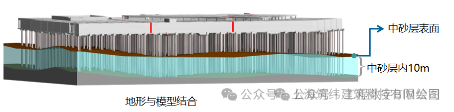
As required by the design, the depth to which the pile shaft enters the fourth medium-sand layer shall not be less than 10 meters. Statistics of pile length by traditional methods are relatively imprecise. Therefore, based on geological survey data and their variations, a geological model is established and combined with the pile-foundation model to accurately determine the bottom elevation at which the pile base extends 10 meters into the medium-sand layer, thereby confirming the pile-shaft length, facilitating control of engineering quantities, and enabling reasonable construction organization.
• Detailed Design of Brick Formwork
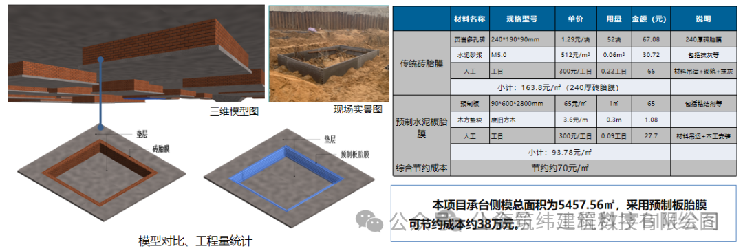
Precast cement boards are used in place of traditional foundation brick formwork as side formwork for pile caps, eliminating the need for masonry and plastering and greatly improving construction efficiency. Using precast-board formwork also saves considerable labor costs: whereas traditional brick formwork requires 15 or more workers for continuous masonry, board formwork requires only about 5 workers for continuous installation, saving roughly half the construction period compared with traditional brick formwork.
• Detailed Design of Formwork and Scaffolding
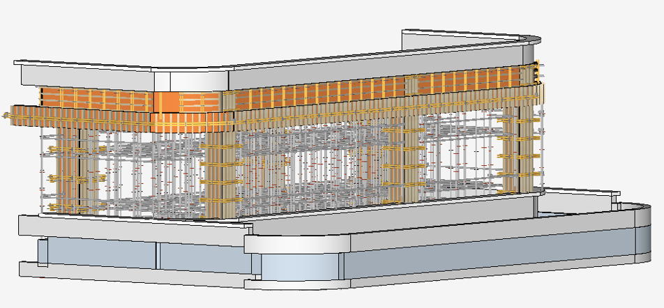
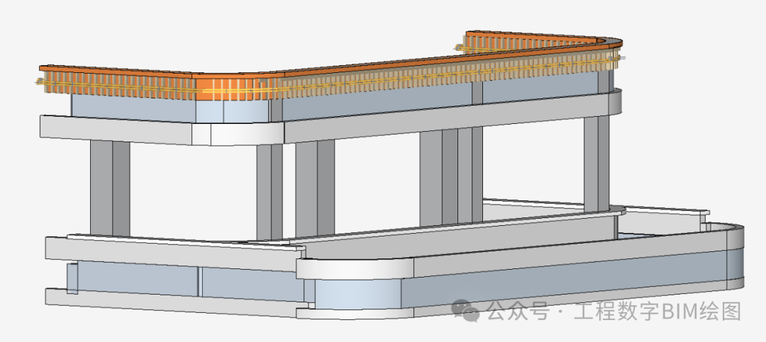
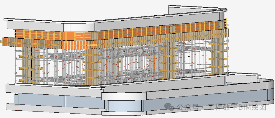
Scaffolding and formwork models are set up according to code requirements to guide on-site construction, while turnover materials and processing lists for each component are quickly extracted for three-dimensional technical briefing. The timing, quantity, and turnover batches of materials delivered to the site are reasonably adjusted according to the construction schedule for precise control.
Using BIM formwork-and-scaffolding software, refined modeling of the formwork support and analysis and verification of the erection scheme are carried out to obtain a scientific and reasonable formwork-support construction scheme. Finally, the calculation report is exported and formwork-support quantities are tallied, providing technical support for project construction.
|
|
• Detailed Design of Beam-Column Joints
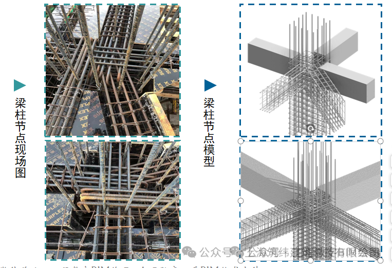
At many locations in the medical-technology building and the inpatient building, the reinforcement arrangement of beam-column joints is dense and interlaced, with multiple clashes. By accurately modeling the beam-column joints and simulating the column-reinforcement layout based on the beam-reinforcement positioning, the clashes are resolved through the detailed arrangement of column reinforcement, providing convenience for on-site construction.
• Detailed Layout of Composite Slabs
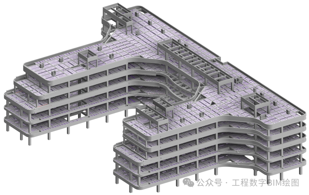
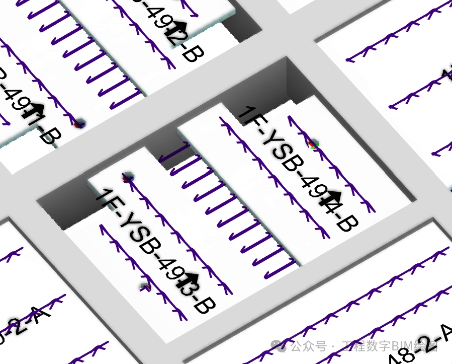
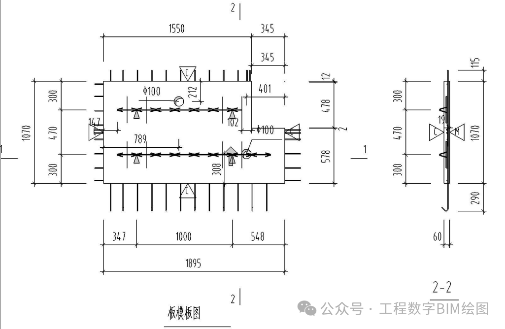
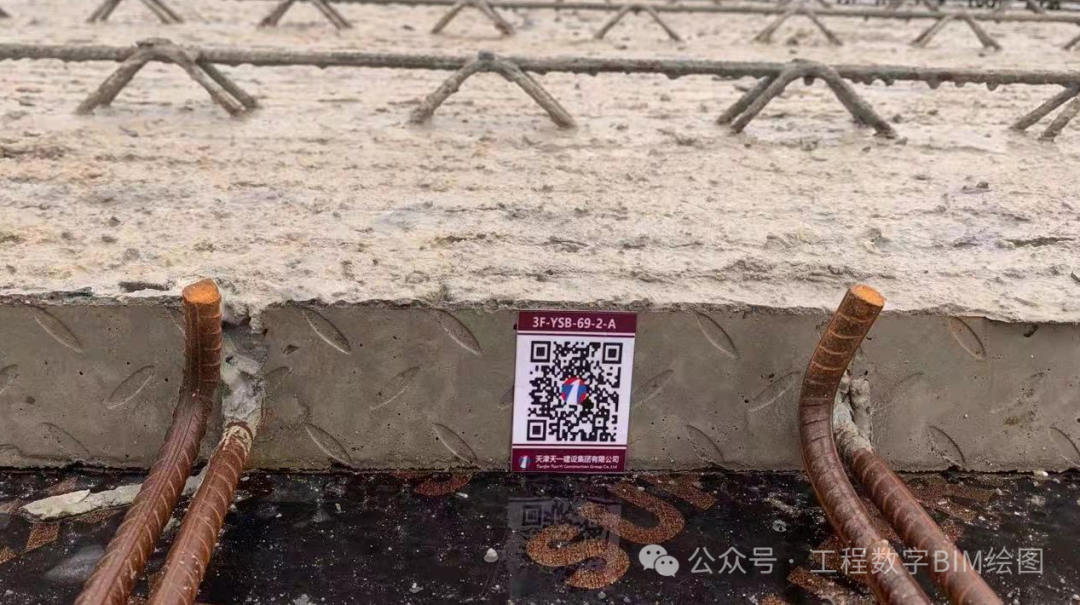
Through the detailed layout of the composite-slab model, each slab is numbered one by one. To avoid later secondary drilling, reserved openings are uniformly positioned in coordination with all discipline systems, standardized production is carried out in coordination with the processing plant, and QR codes are used for information tracking.
A total of more than about 5,000 composite-slab production and processing drawings were exported for this project.
| ||
|
|
|
• Detailed Design of Partition Wall Panels
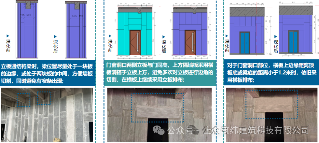
The precast partition wall panels selected are of specifications 600*3000 and 600*2700. For wall heights, standard panels and cut panels are joined in two pieces, and adjacent partition wall panels should be joined with staggered joints of 300 mm.
The vertical panels on both sides of door and window openings are the same height as the doors; the partition wall panels above use horizontal panels laid fully across the top of the vertical panels, avoiding repeated cutting of the corners of the vertical panels. Vertical panels are then arranged on top of the horizontal panels, facilitating construction;
After the layout is completed and verified on site, a total of 365 construction drawings are exported, including 20 plan drawings and 345 section and node detail drawings.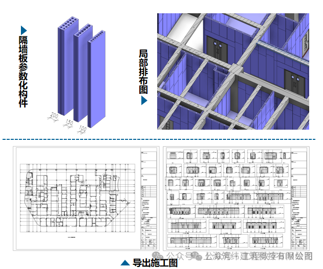
• Detailed Design of Curtain-Wall Embedded Parts
By placing curtain-wall precast embedded parts and curtain-wall mullions in the model, 41 problems were identified, such as clashes between embedded parts and the main structure, incorrect elevations of embedded parts, inconsistencies between the section drawings of embedded-part nodes and the facade detail drawings, and misalignment between curtain-wall mullions and embedded parts. After communication with the designer, the positions of the embedded parts were adjusted in three-dimensional space and drawings were exported directly, avoiding the defects of two-dimensional planar design.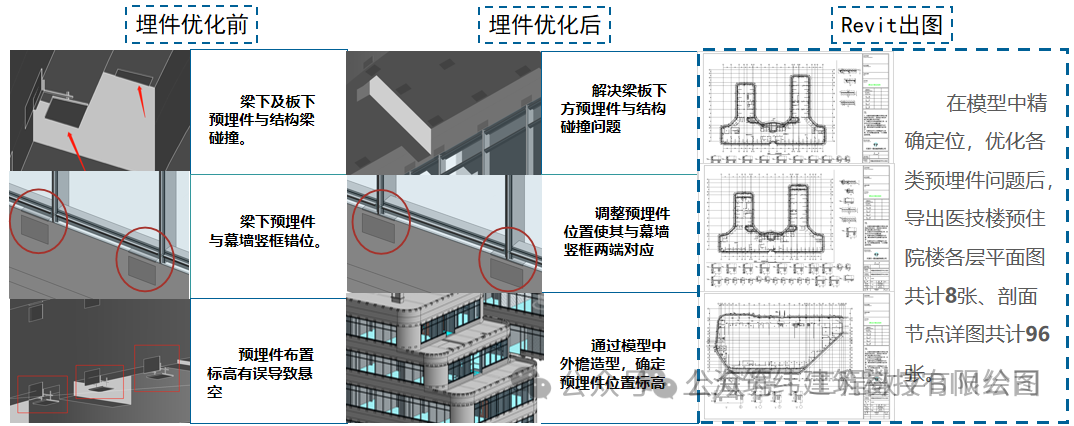
• Detailed Design of Aluminum Panels
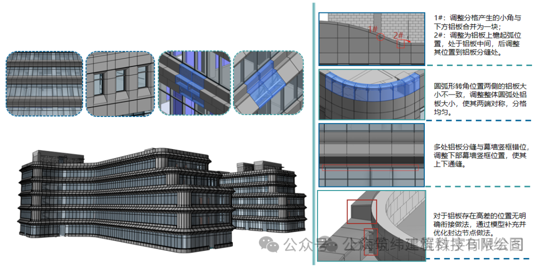
The aluminum panels of the curtain-wall exterior finish are detailed, the positions of embedded parts are further adjusted, and the curtain-wall design effect is previewed intuitively in three dimensions. Problems such as staggered joints and uneven panel divisions are corrected to ensure that the curtain-wall project achieves excellence in one pass.
• Detailed Tile-Layout Design for Interior Fit-Out
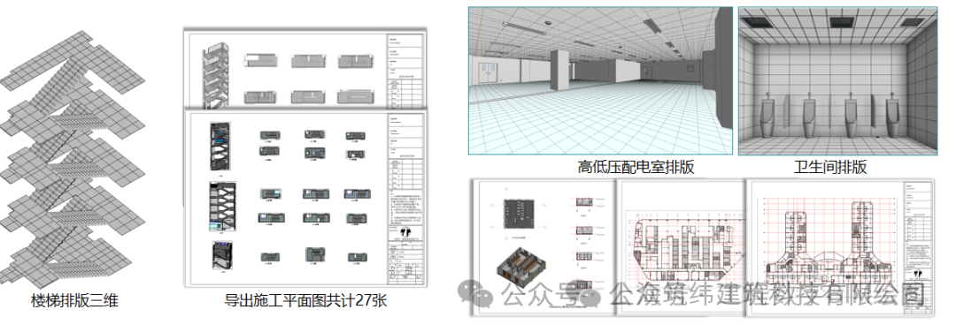
Leveraging the three-dimensional visualization of BIM technology, the interior finish tiles in stairwells are laid out so that the tile joints of the landing platforms and stair flights are centered or continuous, thereby determining the tile specifications, ensuring aesthetics after completion, avoiding material waste, and improving construction efficiency.
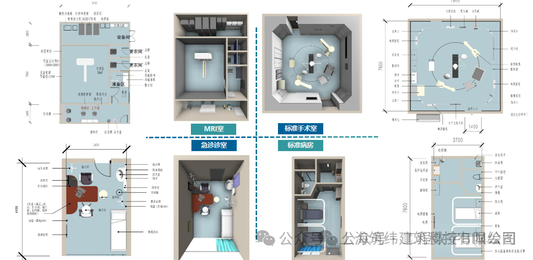
• Detailed Design of Specialized Medical Rooms
03
Specialized M&E BIM Applications
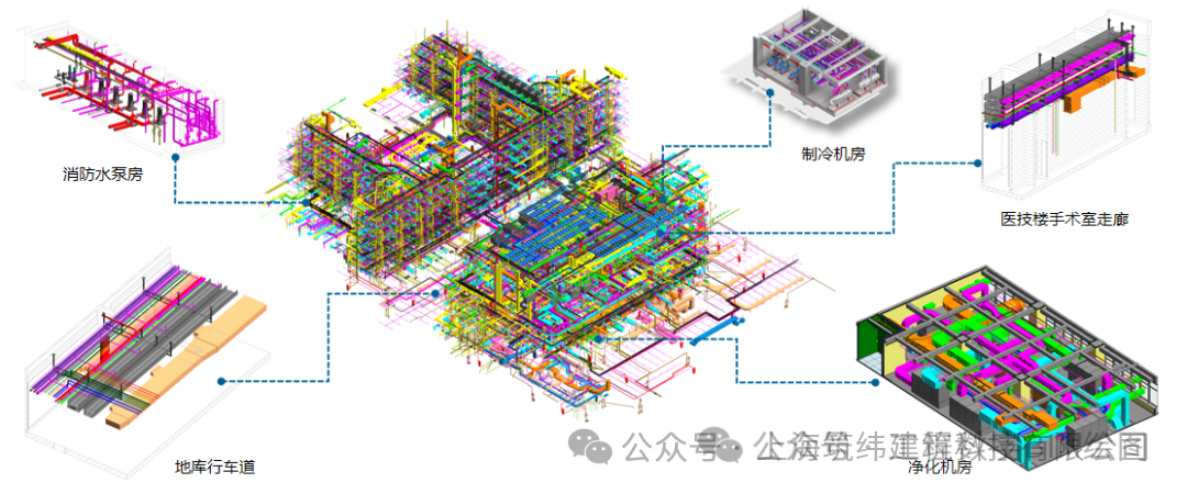
The total M&E detailed-design area of Plots A and B in this project is 83,000 square meters, with 11 large equipment rooms. Among them, the underground garage and the medical-technology building have numerous specialized pipelines. In addition to conventional M&E pipelines, there are many specialized medical systems. The pipelines are dense, the layout space is narrow, with up to 8 layers of pipelines, many decoration-layer nodes, and high ceiling-elevation requirements. At the same time, to realize a smart hospital, the model precision and pipeline-coordination difficulty are high, and construction coordination is difficult. The BIM model is used to optimize the comprehensive pipeline layout and produce BIM construction drawings, so that all pipes are coordinated and arranged in an orderly, staggered manner, effectively saving the construction period, avoiding rework, and improving overall construction quality.
• Clear-Height Analysis
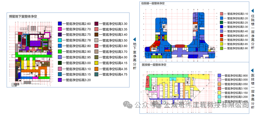
Before the interior fit-out drawings were finalized, the comprehensive pipeline layout was detailed for all areas of Plot A requiring fit-out ceilings, clear-height analysis was performed for all corridors and functional areas, and clear-height analysis drawings were generated. The layout results were briefed to the client and the fit-out designer, and all design units were coordinated to complete the fit-out design drawings.
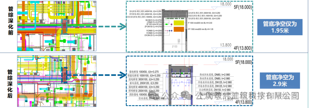
Taking the corridor outside the purification air-conditioning machine room on the fourth floor of the medical-technology building as an example: the fourth-floor story height is 4.2 meters, the maximum beam depth is 0.75 meters, the corridor width is 2.1 meters, and this area has a lowered slab with a drop of 0.2 meters, leaving only 3.4 meters of clear space below the beam. At the same time, the fit-out ceiling height required for this area is 2.75 meters. After the initial layout, the clear space below the pipes was only 1.95 meters. After communication with the client and the designer, the pipeline layout was refined: the smoke-exhaust and exhaust-air ducts were moved into the rooms, and the duct cross-section dimensions and branch routes were changed. After optimization, the pipe-bottom elevation in the corridor is 2.9 meters, meeting the fit-out ceiling requirement. Through precise BIM modeling to determine pipeline installation positions and elevations, the construction schedule is accelerated and construction costs are reduced while meeting the fit-out ceiling requirement.
• Force Analysis of Supports and Hangers
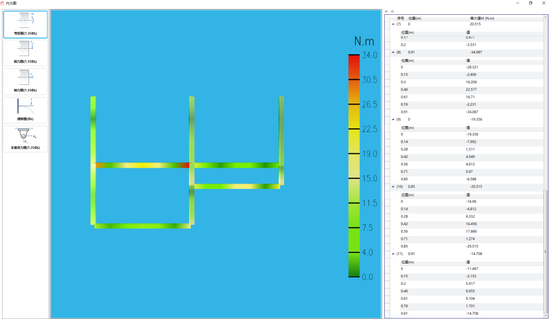
This project has a large number of pipes, so analyzing the forces on supports and hangers is especially important. Using BIM technology and referring to design codes, the selection and arrangement of comprehensive supports and hangers for the underground garage and above-ground main pipelines are designed. Based on the codes and load analysis, the safety and reasonableness of the support-and-hanger arrangement scheme are ensured.
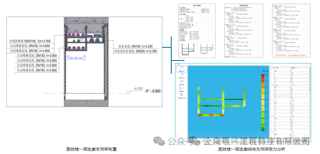
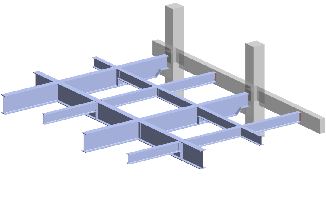
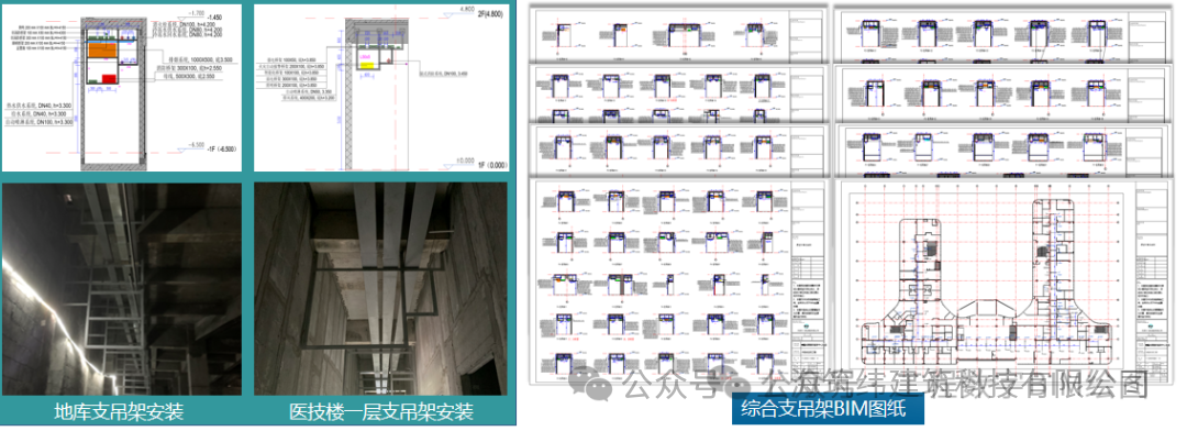
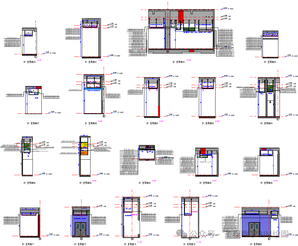
Comprehensive supports and hangers are used in construction, replacing traditional support-and-hanger forms with neatly arranged comprehensive supports and hangers, reducing the number of supports and hangers and making pipeline routing clearer. The detailed design of comprehensive supports and hangers follows a 'one support, one drawing' approach, precisely positioning the location and form of comprehensive supports and hangers in the model, performing force analysis on different forms of comprehensive supports, and positioning the pipelines for each comprehensive-support section, with annotations of pipeline information, support positioning, and support model, to ensure the accuracy of support fabrication and installation. A total of 1,249 support-and-hanger sections were produced for this project.
• Vertical Layout
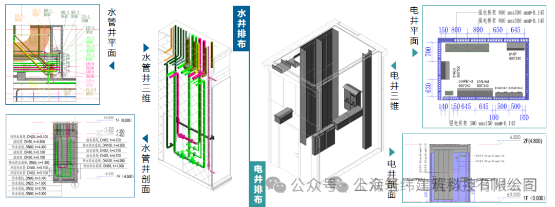
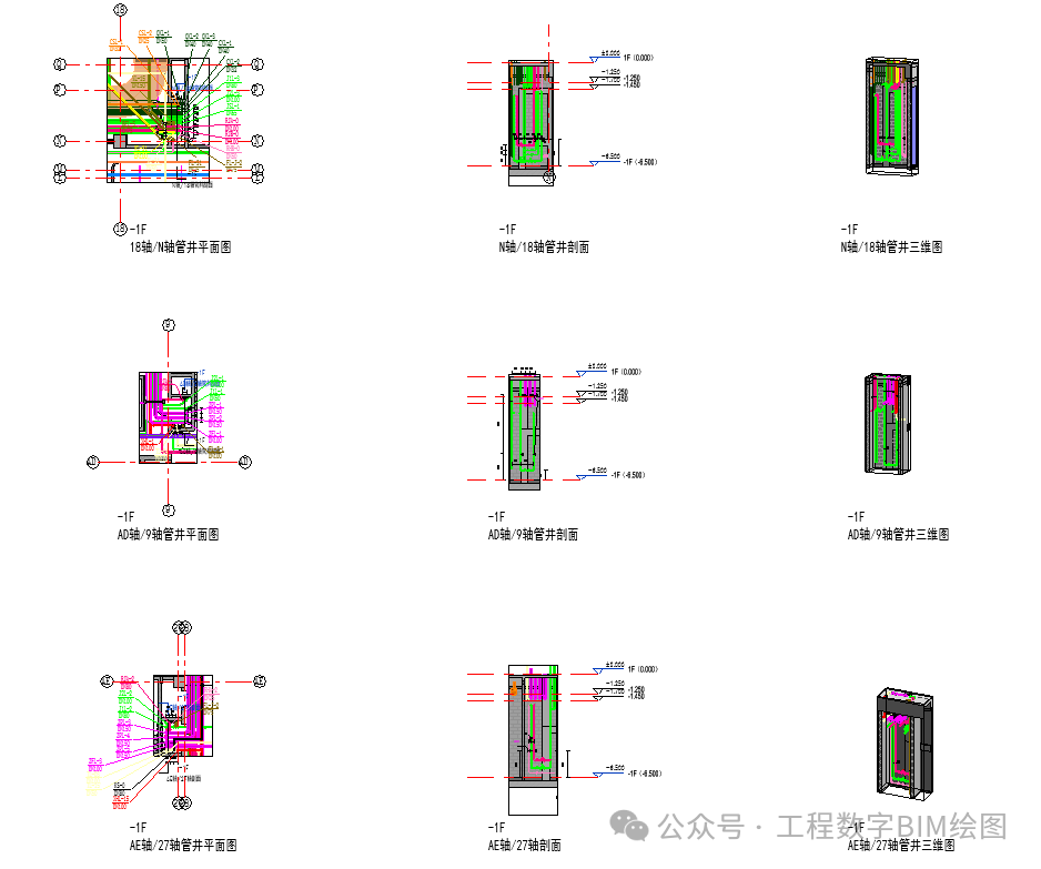
Leveraging the three-dimensional visualization of BIM technology, and considering factors such as the installation positions of water meters and valves and the pipeline insulation thickness, the comprehensive pipeline layout is carried out for all pipe shafts in Plot A. At the same time, the vertical cable trays, distribution boxes, and busbar positions in the electrical shafts of Plot A are arranged, the installation heights and positions of the paired distribution boxes are determined, and the optimal scheme is produced for on-site construction, greatly improving installation progress, saving the construction period, and reducing costs. A total of 13 pipe-shaft and electrical-shaft drawings were produced.
• Structural Reserved Openings
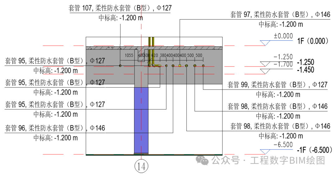
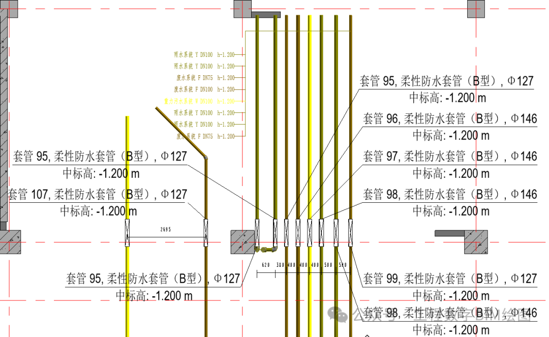
Based on the clash-detection results, the pipeline layout is adjusted and optimized. The installation positions of the pipelines can be intuitively and accurately located in the model, and the structural reserved openings are rechecked.
For the basement of this project, a total of 2 reserved-opening plan drawings and 24 reserved-opening section drawings were produced, with 221 sleeves in total.
|
Annotated Section Drawing of Structural Reserved Openings |
|
| Annotated Plan Drawing of Structural Reserved Openings |
• Equipment Rooms:
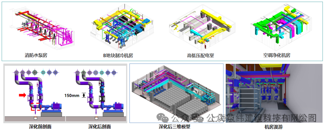
In terms of machine-room detailed design, BIM technology was used to position the equipment of the project's 11 machine rooms before main-structure construction, while optimizing and adjusting the installation spacing of sumps, drainage channels, valves, and instruments. While meeting the requirements of maintenance space, installation space, and construction-acceptance codes, the machine-room optimization effect was experienced immersively through a machine-room walkthrough animation to determine the final scheme and improve the overall visual effect of the machine rooms.
• M&E Drawing Output:
Based on the BIM model, this project assists on-site pipeline installation and comprehensive pipeline-coordination work. The M&E engineering covers HVAC, water supply and drainage, electrical, fire protection, purification engineering, medical gases, pneumatic logistics, and other disciplines. After the comprehensive pipeline coordination is completed, refined drawings are produced from the model for application in on-site construction.
A total of 183 plan and section drawings were produced for Plot A of this project.
|
| Pipe-Shaft Drawing Output |
|
| Section Drawing Output |
END
The views expressed are the author's own Copyright © Zhuwei Architectural Technology
Reproduction without authorization is prohibited
Please credit the source when reposting: Zhuwei Architectural Technology
Zhuwei Architectural Technology is a new-type technical services company specializing in integrated design optimization, BIM consulting and prefabricated construction design consulting. Our team brings together senior engineers from leading design institutes, former executives of real-estate companies, BIM engineers and prefabrication engineers, delivering integrated design optimization, refined drawing review, BIM consulting with MEP detailing, and prefabricated design services.
Design optimization consulting: Positioned as an extension and complement to the design management of real-estate developers, we focus on consulting and optimization for civil buildings. Across the whole process — or at key stages required by the client — we control the economy, rationality and safety of the design, eliminating unnecessary cost while measurably improving drawing quality, achieving "lower cost, higher efficiency".
BIM consulting: Through digital construction technology we help designers reduce errors and improve quality in the design phase, help contractors save cost and plan high-quality MEP installation in the construction phase, and extend BIM models into facility management for the operation phase — in collaboration with mainstream software vendors.
Prefabricated design consulting: Whole-process design on BIM platforms, using Revit and Tekla for PC detailing. Component geometry and reinforcement are linked parametrically — what you see is what you get. We deliver Industry 4.0-ready drawings with cut-length data for every rebar, and IoT-enabled support for production, storage, transport and installation of PC components.
Our expert team comes from leading design institutes, with deep technical grounding and extensive experience in dual-track design and optimization; its technical capability and control are industry-leading.
—— This article is auto-synced from the WeChat Official Account “Zhuwei Architectural Technology”. Read the original ——