BIM Level 3 MEP: Five Methods for Clearance Height Analysis
WeChat Sync · Xiaowei · 2023-12-21
The following article is fromChina BIM Certification Exams
For the BIM Level 3 (Equipment) exam, a common application point - and a mandatory one - is clear-height analysis.
This article summarizes the practice of clear-height analysis for M&E pipelines.
What is clear-height analysis?
In engineering, the clear height is the vertical distance from a floor or ground surface to the underside of the slab above or to the underside of the suspended ceiling.
The calculation rules in the Code for Calculation of Building Area GB/T 50353-2005 mostly use clear height; subsequently, the Code for Calculation of Building Area GB/T 50353-2013 changed the basis for calculating building area to structural clear height, which is defined as the vertical distance from a floor or ground surface to the underside of the structural layer above.
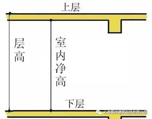
So-called clear-height analysis uses BIM-based virtual construction to perform clear-height (clear-space) analysis in areas with limited space, dense pipelines or high clear-height requirements, so as to identify locations that fail to meet the clear-height requirements early, avoid later design changes, and thereby shorten the schedule and save cost.
Clear-Height Requirements
1. Office buildings
According to clause 4.1.1 of the Design Code for Office Buildings JGJ 67-2006, the clear height of office buildings shall not be lower than 2.70 m for Class I office buildings, 2.60 m for Class II office buildings and 2.50 m for Class III office buildings. In office buildings, the clear height of corridors shall not be lower than 2.20 m and that of storage rooms shall not be lower than 2.00 m. 2. Hospitals
According to clause 5.19 of the Code for Design of General Hospital GB 51039-2014, the indoor clear height shall comply with the following: 1. Consulting rooms should not be lower than 2.60 m, wards not lower than 2.80 m and public corridors not lower than 2.30 m; medical technology departments should be determined according to need.  3. Residential buildings
According to the Design Code for Residential Buildings GB 50096-2011: in ordinary residences, the indoor clear height of bedrooms and living rooms (halls) shall not be lower than 2.40 m, and the local clear height shall not be lower than 2.10 m, and the area with the reduced height shall not exceed one-third of the usable floor area. Where the space within a pitched roof is used as a bedroom or living room (hall), the indoor clear height over half of the area shall not be lower than 2.10 m. The indoor clear height of kitchens and bathrooms shall not be lower than 2.20 m. In kitchens and bathrooms, the clear distance from the underside of the drainage horizontal pipe to the floor or ground surface shall not be less than 1.90 m and shall not affect the opening of doors or windows. Value of Clear-Height Analysis
1. Clear-height analysis refers to using BIM-based virtual construction during the design stage to perform clear-height (clear-space) analysis in areas with limited space, dense pipelines or high clear-height requirements, so as to identify locations that fail to meet functional and aesthetic clear-height requirements early, avoid later design changes, and thereby shorten the schedule and save cost.
2. Without BIM, we would only discover during M&E installation - after the civil and structural works had been completed - that the clear height in certain locations no longer met the requirements, or was even extremely low, at which point adjustment would be practically impossible.
Five Methods of BIM Clear-Height Analysis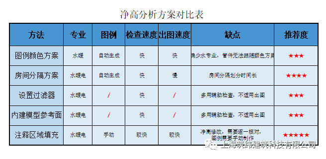 The five methods are as follows
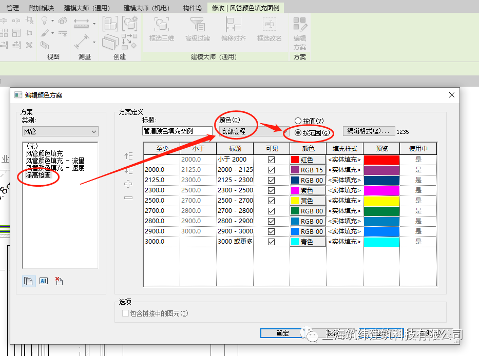
1. Legend Color Scheme
Analyze tab → Duct Legend → Edit Scheme → 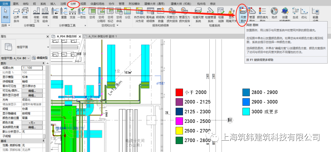 Duplicate Scheme → Assign Title → By Range → select Bottom Elevation as the parameter → assign height parameter and color fill
 2. Room Separation Scheme
Architecture tab → Rooms & Areas → Color Schemes → 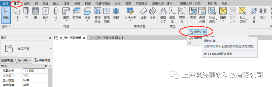 Duplicate Scheme → Assign Title → By Range → select Area as the parameter → assign color fill
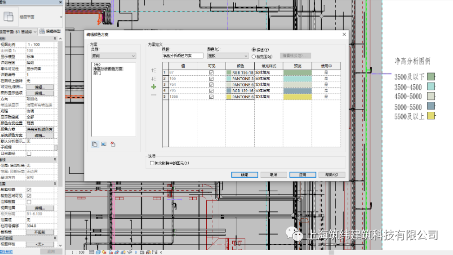 3. Set Up Filters
View tab → Filters → Add → Duplicate Filter → filter condition: greater than or equal to the lower value and less than the upper value → add color fill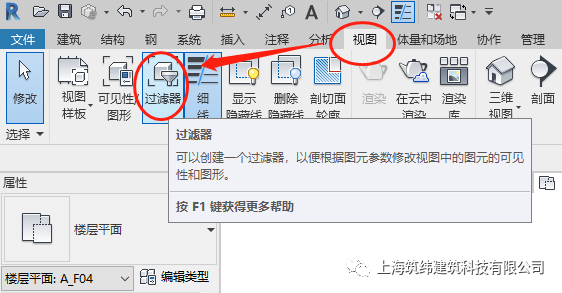
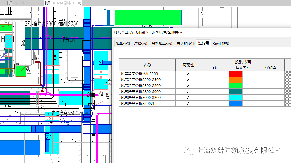 4. In-Place Model Reference Plane
Architecture tab → Component In-Place → Generic Model → draw a slab as a reference plane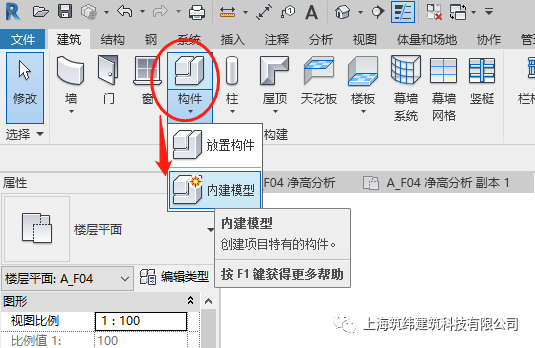
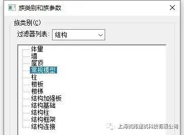
→ assign a highly visible material color → so that pipelines below the reference level can be easily reviewed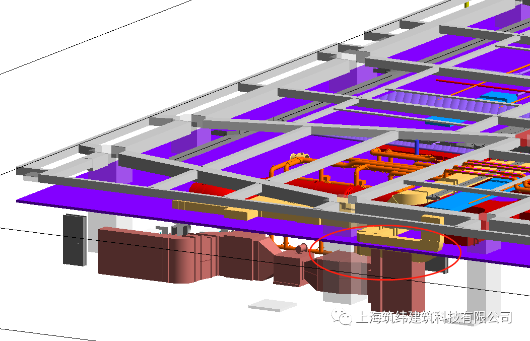
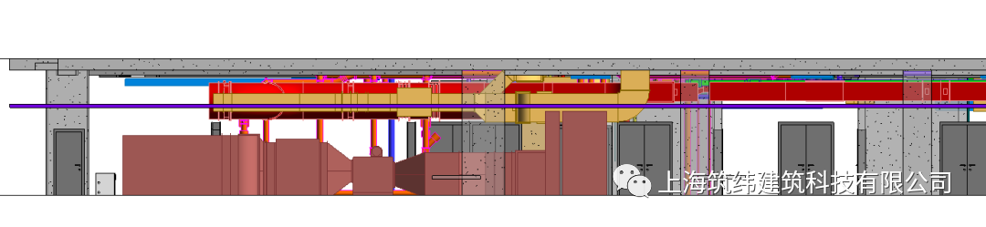 The advantage of an in-place model is that the thickness and height of the reference plane can be freely adjusted; if a floor slab is used to draw it, the filter will show the roof slab, which is inconvenient to view.
5. Annotate Filled Region
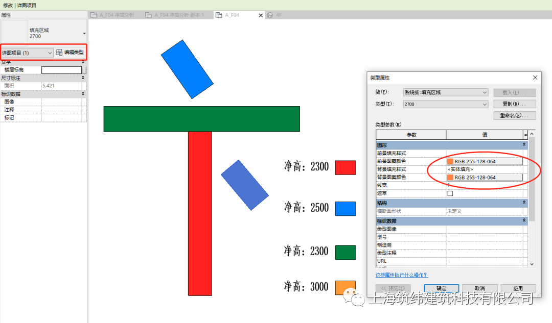
Annotate tab → Region → Filled Region → pick the building outline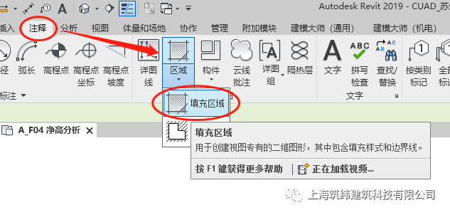 Duplicate the filled region → assign a color fill (background-color fill is recommended; place the architectural base drawing on top so that room outlines can be picked easily)
 Other methods, such as schedules, Dynamo and MagiCAD, and plug-ins such as Glodon, Hongye, Hongwa and Pinming, are not demonstrated here; this article lists only the native Revit methods.
END
The views expressed are the author's own Copyright © Zhuwei Architectural Technology
Reproduction without authorization is prohibited
Please credit the source when reposting: Zhuwei Architectural Technology
Zhuwei Architectural Technology is a new-type technical services company specializing in integrated design optimization, BIM consulting and prefabricated construction design consulting. Our team brings together senior engineers from leading design institutes, former executives of real-estate companies, BIM engineers and prefabrication engineers, delivering integrated design optimization, refined drawing review, BIM consulting with MEP detailing, and prefabricated design services.
Design optimization consulting: Positioned as an extension and complement to the design management of real-estate developers, we focus on consulting and optimization for civil buildings. Across the whole process — or at key stages required by the client — we control the economy, rationality and safety of the design, eliminating unnecessary cost while measurably improving drawing quality, achieving "lower cost, higher efficiency".
BIM consulting: Through digital construction technology we help designers reduce errors and improve quality in the design phase, help contractors save cost and plan high-quality MEP installation in the construction phase, and extend BIM models into facility management for the operation phase — in collaboration with mainstream software vendors.
Prefabricated design consulting: Whole-process design on BIM platforms, using Revit and Tekla for PC detailing. Component geometry and reinforcement are linked parametrically — what you see is what you get. We deliver Industry 4.0-ready drawings with cut-length data for every rebar, and IoT-enabled support for production, storage, transport and installation of PC components.
Our expert team comes from leading design institutes, with deep technical grounding and extensive experience in dual-track design and optimization; its technical capability and control are industry-leading.
—— This article is auto-synced from the WeChat Official Account “Zhuwei Architectural Technology”. Read the original ——